

Content last revised on September 23, 2026
Preventing Spurious Faults: Mitigating Hard-Switching Transients in the FF500R12KE4
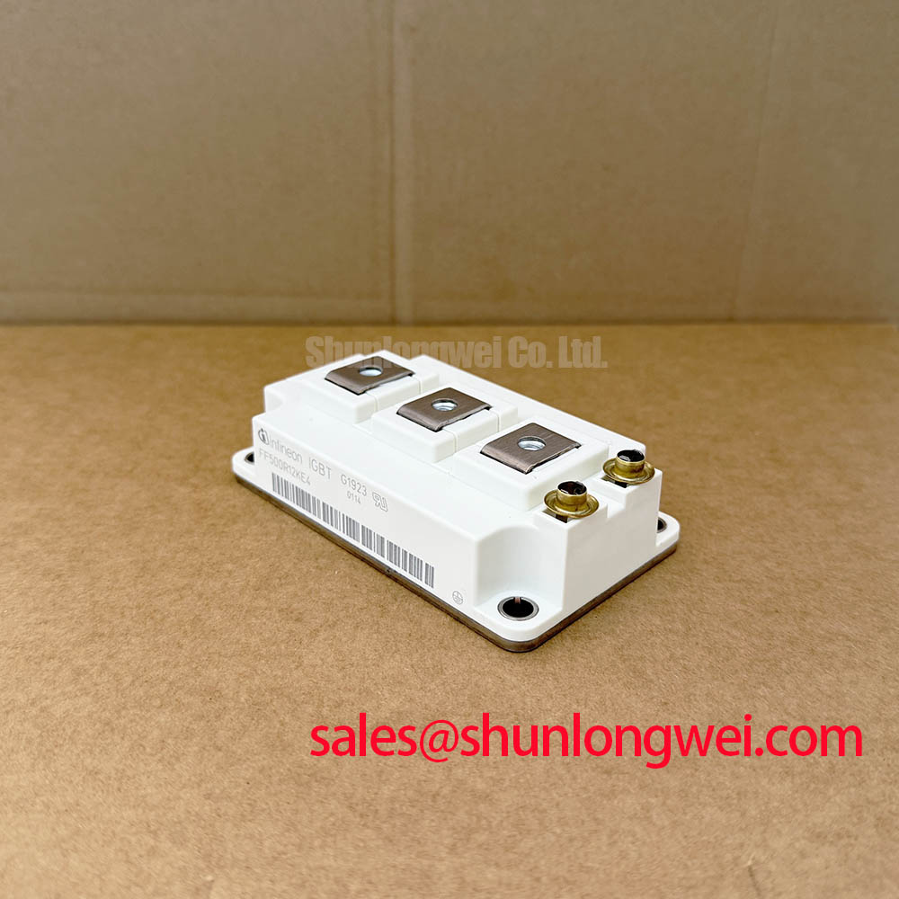
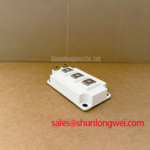
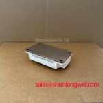
Before reconnecting a replacement module, isolate the DC link, verify discharge using the equipment’s approved procedure, and compare the cold-state terminal readings with the original converter schematic and a known-good phase position where available. The FF500R12KE4 is an Infineon IGBT module rated at 1200 V VCES and 500 A continuous DC collector current at TC = 100°C, both Official Datasheet Specifications. Its 62 mm C-Series housing must match the existing mechanical footprint, power-terminal arrangement, gate-drive connector arrangement, and converter control architecture before an in-position replacement is considered.
Hard-switching failures often begin with a waveform problem rather than an immediately visible package defect. During turn-off, inductance in the commutation loop can create collector-emitter overshoot as current falls. Gate-loop inductance can also couple switching activity back into the gate circuit, producing ringing or an unintended gate pulse. A controller may interpret these events as overcurrent, desaturation, or gate-drive failure even when the module itself is not the original source of the shutdown.
The 1.75 V typical VCE(sat) at TVJ = 125°C is an Official Datasheet Specification used for conduction-loss assessment under its stated test conditions. It should not be treated as a fixed in-circuit diagnostic threshold. A measured collector-emitter voltage in operating equipment is affected by current, junction temperature, gate-drive condition, probe placement, switching state, and the accuracy of the sensing circuit.
For a stopped converter, inspect gate and emitter control terminals for loosened connector retention, contamination, bent contacts, or insulation damage. Then examine the laminated busbar, DC-link terminals, snubber path, and gate-driver return routing. A missing fastener, disturbed busbar stack, or extended driver lead can change the parasitic inductance seen by the switching loop. Design Consideration: keep the gate-drive return physically associated with its gate path and minimize the commutation-loop area to suppress turn-off inductive overshoot. The system engineer should verify peak collector-emitter voltage and gate-emitter behavior with correctly rated differential and isolated probes during controlled switching tests.
Short-circuit protection must be evaluated as a complete drive-system function rather than assigned to the IGBT module alone. Type I and Type II short-circuit events have different current-rise conditions, but both demand a protection path that detects the abnormal state, inhibits the drive command, and removes gate charge in a controlled manner. Where a driver uses desaturation sensing, the sensing network, blanking logic, gate resistor arrangement, and soft-turn-off profile must be checked against the original drive documentation. A two-stage soft turn-off approach can reduce the risk of a severe inductive overvoltage when a fault is interrupted, but its timing and gate-current profile remain system-determined.
When evaluating a converter repair, compare module part number, voltage class, current rating, package family, terminal geometry, driver compatibility, and thermal interface requirements as a set. A higher-current package is not automatically an in-position substitute. For systems where a different high-current Infineon module is being evaluated at engineering level, FZ3600R12HP4 should be assessed only against the actual converter topology, mounting arrangement, cooling plate, gate-driver capability, and protection validation requirements.
Assembly Integrity & Layout Architecture: Calculating Failure-in-Time Rates for the FF500R12KE4
The module nameplate should be checked against the converter bill of materials before any FIT or high-altitude reliability discussion begins: FF500R12KE4, 1200 V, 500 A at TC = 100°C, and 150°C maximum operating junction temperature are the relevant Official Datasheet Specifications supplied for this device. These parameters define important electrical and thermal boundaries, but they do not provide a site-specific failure-rate prediction for a completed wind converter.
Terrestrial neutron exposure, DC-bus operating voltage, switching transients, enclosure environment, operating altitude, and mission profile can influence a system-level reliability assessment. No numerical FIT rate, single-event burnout rate, altitude derating factor, or service-life figure should be assigned to this module without an applicable manufacturer source and a defined system operating profile. Design Consideration: equipment operating at elevated locations should be reviewed by the system owner against the applicable converter design rules, DC-link conditions, protection response, and environmental qualification evidence.
A practical field inspection starts with mechanical evidence. Look for uneven pressure marks from the heatsink interface, signs of busbar movement, cracked support hardware, disturbed gate-driver connectors, and discoloration around adjacent fuses or snubber components. These observations do not prove a single failure cause, but they identify areas requiring waveform checks and insulation inspection before another module is energized.
The driver’s desaturation protection path deserves particular attention after an IGBT event. Confirm that the collector sensing connection reaches the intended device node, that the return reference is intact, and that the driver fault output reaches the converter controller. The original driver documentation should define detection blanking and protection timing. It is unsafe to assume that a generic short-circuit detection target applies to every FF500R12KE4 installation, because the allowable response is governed by the complete driver, busbar, DC-link, fuse coordination, and fault-current path.
Fast semiconductor fuse coordination is also a system-level task. Fuse selection cannot be made from the module’s continuous current rating alone. Engineers should review the converter’s fault-current waveform, the fuse time-current and energy characteristics, DC-link stored energy, and the interruption capability of the surrounding hardware. The purpose is to limit damage propagation after a severe internal or external fault; it does not replace active gate-drive protection.
For a broader technical framework covering voltage selection, switching stress, thermal limits, and reliability verification, consult the Power Electronics Masterclass. For device-family background, Infineon’s TRENCHSTOP™ IGBT3 application material and EconoDUAL™ 3 product information provide useful manufacturer context for high-power IGBT module integration.
Benchtop Waveform Tuning: Reinforced Insulation Barrier Integrity for the FF500R12KE4
Do not begin waveform tuning until the converter’s control supply, gate-driver isolation arrangement, protective earth path, and probe configuration have been verified. The FF500R12KE4 is a power module, not a complete isolated gate-drive assembly. Reinforced isolation voltage capability and common-mode transient immunity are properties that must be confirmed for the selected driver, isolated power supply, sensing interface, PCB spacing, and assembled equipment. They must not be attributed to the module without an applicable official specification.
When a converter trips only during rapid current transitions, capture the gate-emitter voltage, collector-emitter voltage, driver supply rails, desaturation signal, and controller fault signal together. A gate waveform that appears clean at the driver output can look materially different at the module terminals because of cable inductance, connector condition, return-path routing, and measurement reference errors. Compare the affected phase with a healthy phase under equivalent operating conditions where this can be done safely.
The supplied 3.70 µC gate charge is an Official Datasheet Specification. It helps the drive-system designer understand the charge that must be moved under the datasheet test conditions, but it does not establish an approved gate resistor, switching frequency, or turn-on and turn-off timing for every converter. Engineering Recommendation: tune the existing drive network only through controlled tests that verify device voltage stress, gate ringing, current sharing, EMI behavior, and protection response across the intended operating range.
Inspect isolation barriers and control wiring for moisture tracks, abrasion, trapped metal debris, poor connector seating, and clearance changes caused by service work. These conditions may cause nuisance trips, unstable sensing, or intermittent gate commands. Confirm the repair against the equipment manufacturer’s insulation coordination requirements and applicable safety procedure.
Transient Dynamics & Electrical Design: Baseplate Flatness and Screw Installation for the FF500R12KE4
The thermal path should be inspected before the replacement module is installed. The FF500R12KE4 has an Official Datasheet Specification of 0.046 K/W thermal resistance from junction to case per IGBT. This value describes the device under stated datasheet conditions; it does not include thermal interface material, heatsink flatness, coolant condition, mounting pressure, or external thermal resistance. Junction temperature margin in service depends on the complete heat-removal assembly.
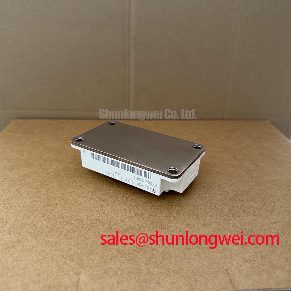
Clean the heatsink contact surface using an approved process, inspect it for raised damage or foreign particles, and apply the selected thermal interface material evenly in accordance with the equipment documentation. Excess material can increase thermal resistance, while insufficient coverage can leave local dry areas. Baseplate flatness and heatsink flatness should be evaluated together because uneven contact pressure can create localized thermal stress even when the module appears mechanically secure.
Install mounting screws progressively in the sequence specified for the converter assembly so the module seats evenly. The required screw torque, fastener grade, washer arrangement, and tightening sequence should come from the original equipment documentation or the applicable module mounting instruction. ⚠️ Field Alert: Never fully tighten one mounting screw before the others are seated, because uneven clamping can distort the thermal interface and damage the mounting arrangement.
After mechanical installation, confirm that power terminals are properly supported and that busbar stress is not transferred into the module body. Recheck control connectors before applying low-energy commissioning power. During the first controlled energization, observe the converter’s fault records and switching waveforms rather than assuming a successful static meter test proves dynamic compatibility. The module’s 150°C maximum operating junction temperature remains the Official Datasheet boundary, while the permissible operating point must be validated by the converter’s thermal model, cooling condition, load profile, and protection behavior.