Content last revised on October 21, 2026
Preventing Spurious Faults: Driver Power Stage Start-Up Inrush Mitigation Guidelines for FF600R07ME4
Keep the DC link isolated while checking whether both gate-driver channels establish a stable off state before the controller releases its startup interlock. On an FF600R07ME4 installation, capture the auxiliary supply, driver-ready signal, and gate-emitter waveform together; a startup fault can involve supply collapse, unintended gate excitation, or incorrect interlock timing rather than a failed power module.
The Infineon FF600R07ME4 is an IGBT module with official specifications of 650 V collector-emitter blocking voltage and 600 A nominal collector current. The nominal current rating is not an unconditional continuous operating allowance; consult the datasheet conditions and the application’s thermal limits. Its ±20 V gate-emitter peak voltage is an absolute electrical boundary, not a recommended operating command. Engineering Recommendation: establish the off-state bias required by the approved driver circuit, including negative bias where specified, and verify its stability during auxiliary supply startup and shutdown.
Check undervoltage lockout at the driver rather than relying only on a controller status display. The switching command should remain inhibited while the driver supply crosses its operating threshold. If the auxiliary supply repeatedly restarts, investigate its loading, startup behavior, and connector resistance before changing gate resistors. Keep gate and return conductors closely associated, and assess clearance against the actual working voltage and equipment insulation requirements.
Design Consideration: gate-driver sequencing and DC-link precharge solve different problems. A stable gate supply helps prevent unintended switching; the precharge circuit limits capacitor charging current. Inspect the precharge resistor, bypass contactor sequence, and bus-voltage feedback separately. The module’s official 1200 A repetitive peak collector current must not be interpreted as an unrestricted startup surge allowance or short-circuit protection specification.
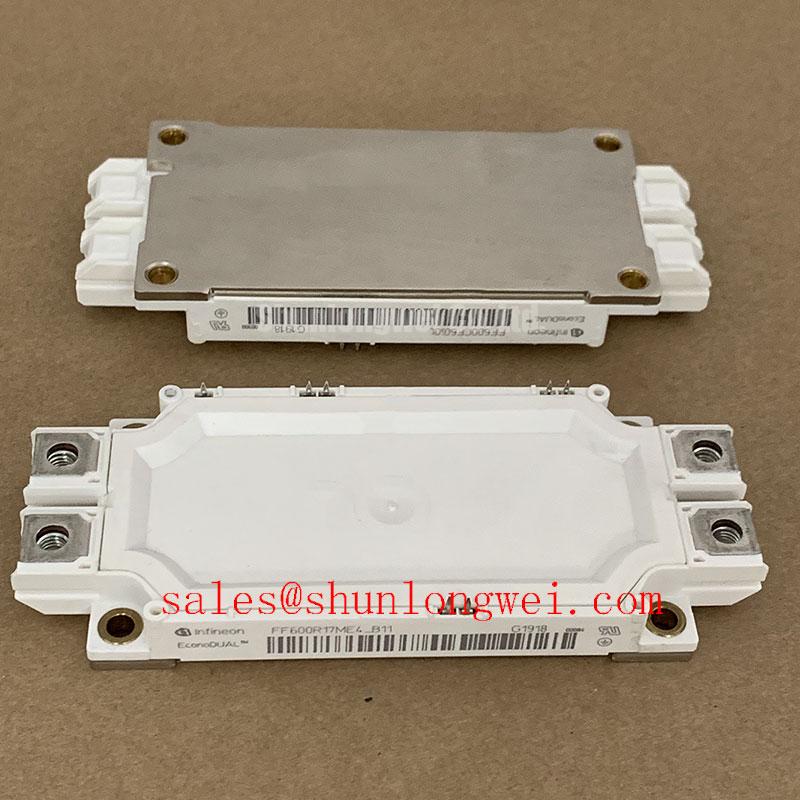
For identification and purchasing records, retain the complete FF600R07ME4 product reference alongside the equipment schematic and driver-board revision. This keeps the electrical assessment tied to the actual assembly rather than to a current rating alone.
Assembly Integrity and Layout Architecture: Transmission-Line Mismatch Assessment for FF600R07ME4
Measure the inverter switching node and motor-terminal waveform separately when long motor leads accompany unexplained overvoltage trips. Design Consideration: cable reflections arise from impedance discontinuities, and the voltage at the motor termination can differ substantially from the waveform measured at the module. Distinguish reflected motor-terminal voltage from collector-emitter overshoot caused by the local commutation loop.
Use appropriately rated differential probes and suitable measurement connections so probe pickup does not become the apparent fault. When evaluating an output choke or dv/dt filter, consider cable characteristics, motor insulation, switching behavior, filter losses, and control-loop interaction. Component sizing belongs to the complete drive design; the module’s blocking rating does not establish a universal cable-length limit or filter value.
Design Consideration: a metal-oxide varistor absorption network requires coordination of clamping behavior, pulse energy, repetition rate, and connection inductance. A remotely connected MOV cannot be assumed to suppress a fast local collector-emitter transient. Review its placement and intended protection role alongside the existing snubber and DC-link network, then verify the resulting waveform under controlled operating conditions.
Replacement assessment also needs an explicit separation between a candidate part and an approved interchange. The following comparison records the established FF600R07ME4 limits without assigning unverified ratings to another module.
| Assessment item | FF600R07ME4 | FF600R12ME4P_B11 candidate |
|---|---|---|
| Manufacturer | Infineon | Infineon |
| Collector-emitter voltage | 650 V, Official Specification | Consult the candidate datasheet for electrical ratings, test conditions, terminal layout, dimensions, and mounting requirements before interchange approval. |
| Nominal collector current | 600 A, Official Specification; operating capability depends on datasheet conditions and thermal limits | |
| Repetitive peak collector current | 1200 A, Official Specification | |
| Total power dissipation | 1800 W at case temperature 25°C, Official Specification | |
| Gate-emitter peak voltage | ±20 V, Official Specification | |
| Isolation test voltage | 4000 V AC for 1 minute, Official Specification |
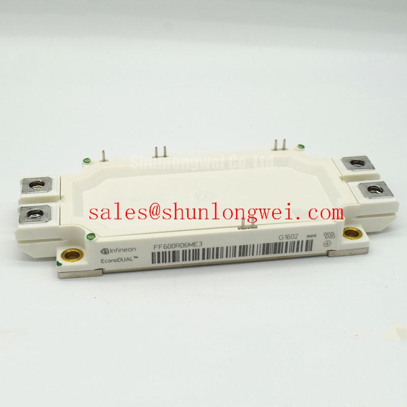
The FF600R12ME4P_B11 is a comparison candidate, not an automatically verified direct replacement. Evaluate its gate-drive requirements, switching losses, mechanical interface, and protection compatibility before approval. A traction-inverter repair assessment for high-speed rail or heavy freight locomotives would additionally require equipment-specific electrical and qualification checks; the FF600R07ME4 ratings alone do not establish suitability.
Engineering Recommendation: coordinate semiconductor fuses using the equipment fault study, prospective fault current, clearing behavior, and manufacturer protection guidance. The 1200 A peak rating is not a fuse-clearing I²t rating. If the surrounding converter includes a controlled front end, the FF600R12KE4 can be evaluated separately as a related power-stage component, not assumed to be a passive rectifier or a matched companion.
Transient Dynamics and Electrical Design: Junction-to-Case Thermal Network Assessment for FF600R07ME4
Reconstruct the load pulse and case-temperature history before judging whether a temporary overload remained within the junction-temperature boundary. The official 1800 W total power dissipation at a case temperature of 25°C is a limiting condition, not a continuous cabinet-level cooling allowance. A heatsink surface reading also does not directly reveal the peak temperature inside an operating junction.
Engineering Calculation: for an isolated rectangular loss pulse under the applicable thermal-model assumptions, the junction rise is estimated as ΔTj = Ppulse × ZthJC(tpulse). Add that rise to the relevant case temperature and compare the result with the manufacturer’s junction-temperature limit. For repeated or irregular pulses, apply the actual loss history to the manufacturer’s transient thermal network; a multi-RC model represents the different thermal response times rather than a single instantaneous temperature rise.
Use the model corresponding to the device being evaluated, and distinguish IGBT losses from diode losses. Switching energy varies with operating conditions, while conduction loss follows the current waveform and temperature-dependent characteristics. Design Consideration: a junction-to-case network stops at the case boundary; the interface material, heatsink, and coolant path need their own thermal treatment.
Inspect the mounting face for contamination, damage, and uneven contact before applying thermal interface material. Engineering Recommendation: use the manufacturer’s application method and fastening sequence, with controlled tightening and a uniform interface layer suited to the mating surfaces. Excess material can increase thermal resistance, while incomplete coverage can leave local contact deficiencies.
Field Alert: follow the module’s specified mounting torque and thermal-interface procedure rather than transferring bolt settings or paste thickness from another housing.
When the equipment uses resonant switching, review current phase and commutation conditions before interpreting thermal results; the discussion of Resonant Topologies in Home Appliances provides contextual topology guidance, not a test standard or an FF600R07ME4 operating approval.
Assembly Integrity and Layout Architecture: Pre-Installation Junction Health Checks for FF600R07ME4
Discharge the DC link, verify absence of voltage, and disconnect paths that would place other components across the FF600R07ME4 before making cold measurements. Map the main terminals and gate connections from the terminal drawing. Keep each gate referenced to its corresponding emitter during main-terminal screening so an inadvertently charged gate does not distort the result.
Engineering Recommendation: use diode-check mode to compare the antiparallel diode paths in their forward and reverse directions, recording instrument polarity and module temperature. Compare corresponding paths under identical conditions. An unexpected low-resistance reading warrants isolation and further testing; it does not, by itself, identify the damaged junction or establish the initiating fault.
A multimeter can reveal gross gate-emitter conduction but cannot certify gate leakage at the specified test voltage, blocking capability, or switching performance. Investigate suspicious results with appropriate current-limited test equipment and the manufacturer’s test conditions. Avoid applying an insulation tester across gate terminals.
The official 4000 V AC isolation test for 1 minute must not be interpreted as an allowable continuous working voltage or isolation between the driver logic and power circuit. Consult the module’s isolation test configuration and the equipment insulation design. The distinction between electrically separated circuits is explained in Galvanic Isolation Principles in High Voltage Power Systems; that general principle does not replace module-specific insulation requirements.
After installation, check terminal seating, conductor strain, protective covers, and gate-connector engagement before controlled energization. Record the cold-screening results with the first driver and switching captures so subsequent troubleshooting can distinguish an assembly change from an operating-condition change.