
Content last revised on October 14, 2026
Field Diagnostics & Commissioning: Thermal Stress Alleviation in Bidirectional FS450R07A2P2_B31 Topologies
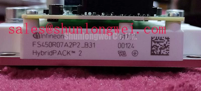
With the DC link isolated and its stored energy discharged, compare the module marking with the equipment service record before reconnecting the power terminals. The Infineon FS450R07A2P2_B31 is an IGBT module. Verify its voltage and current ratings, including their specified conditions, against the manufacturer datasheet. Commissioning also requires agreement between the installed assembly, cooling arrangement, gate driver, and equipment schematic.
For maintenance planning, keep the complete suffix in the replacement record and document the original terminal arrangement before dismantling. The FS450R07A2P2_B31 product page provides the model reference for procurement discussions. Consult the manufacturer datasheet and assembly instructions for terminal assignments, rating conditions, mechanical dimensions, gate limits, and mounting requirements before approving an installation.
Correlate heating with power direction, load transitions, and coolant or airflow conditions rather than treating every temperature alarm as a module fault. As a Design Consideration, a useful commissioning record pairs the equipment load command with measured phase currents, DC-link voltage, heatsink temperature, and available temperature-sensor readings. Measurements taken at comparable operating conditions help distinguish a cooling-path change from a change in electrical loading.
When evaluating this module for a utility-scale centralized battery energy storage PCS, designers should check operation during both charging and discharging, including reactive-power demand where supported by the converter. Four-quadrant converter operation combines active-power direction with reactive-power exchange; it does not mean that active power follows four independent directions. Heavy battery charge or discharge demand can produce repeated changes in semiconductor losses, while the thermal response depends on the converter control and cooling assembly.
Engineering Recommendation: investigate the amplitude and repetition of temperature excursions during representative load transitions. A stable heatsink reading can conceal faster semiconductor temperature changes, so surface measurements should be interpreted alongside the equipment’s validated thermal model and protection records. Avoid assigning a junction temperature directly from an external probe. If heating differs between comparable switching positions, examine current distribution, switching commands, and cooling contact before attributing the difference to the module.
Dust accumulation, obstructed filters, reduced fan performance, and coolant restrictions can change the thermal baseline without changing the commanded load. Record these conditions before cleaning or adjusting the system, then repeat the same operating sequence afterward. Maintenance Note: trend terminal and heatsink temperatures under comparable loads, and check the cooling path before increasing output after a thermal alarm. Maintenance intervals should follow contamination levels and observed trends rather than an invented service-life figure.
Cold starts deserve a separate check where ambient conditions fluctuate. As a Design Consideration, moisture on terminals, control connectors, or nearby insulating surfaces can affect commissioning measurements and electrical clearances. Assess enclosure humidity management and allow condensation to clear under the equipment maintenance procedure before energization. Keep airflow access and service clearance around the mounted assembly consistent with the equipment layout; neither clearance nor environmental capability should be inferred from the package description alone.
FS450R07A2P2_B31 Operational Boundaries: Evaluating Thermal Paste Degradation and Mounting Limits
Inspect the thermal-interface contact pattern when the assembly is removed, looking for uneven coverage, contamination, or displaced material. As a Design Consideration, the interface should fill surface irregularities without creating an unnecessarily thick thermal barrier. Choose its application method and thickness from the approved material and module mounting instructions, not from a universal paste-layer target. A coating that looks uniform before installation can still produce uneven contact after tightening.
Check the mating surface for damage and flatness using the assembly’s specified inspection method. Thermal paste should not be used to compensate for excessive curvature or a damaged cooling surface. Where the contact pattern suggests uneven seating, inspect the mounting interface and hardware before repeating assembly. Clean away old material using compatible procedures, prevent debris from reaching terminals, and retain photographs of the contact pattern for comparison during subsequent maintenance.
Engineering Recommendation: follow the specified tightening sequence and use a calibrated torque tool for each fastening function. Main electrical terminals and heatsink mounting fasteners can have different requirements, so a single workshop torque setting is inappropriate. Progressive tightening, where prescribed, helps establish even seating. Repeated tightening without an approved procedure can disturb the interface or overstress hardware; checks should follow the equipment maintenance instructions rather than an assumed universal retorque schedule.
Parallel operation requires separate attention to static and dynamic current sharing. As a Design Consideration, an IGBT’s collector-emitter saturation voltage can exhibit a positive temperature coefficient in part of its operating range, but the relevant device curves determine where that behavior applies. It should not be treated as proof that parallel modules automatically balance. Compare the applicable electrical characteristics and evaluate sharing under the intended current, temperature, and switching conditions.
Symmetrical busbar paths, comparable thermal contact, and consistent gate-drive connections help reduce avoidable differences between parallel branches. Measure individual branch currents where the equipment permits, because aggregate current can conceal imbalance. A warmer branch may reflect electrical loading, cooling resistance, or measurement location; inspect those factors together. The Infineon IGBT Modules Overview provides manufacturer context for module families, while installation decisions should remain tied to the exact device and assembly documentation.
A cross-model review involving FS75R12KT3G should be treated as a compatibility assessment, not a direct replacement recommendation. Compare electrical ratings, circuit configuration, terminal mapping, gate-drive requirements, cooling interface, and mounting geometry against the existing assembly. A related model name does not establish interchangeability, and matching one headline parameter does not establish a service-compatible replacement.
FS450R07A2P2_B31 Thermal-Electrical Optimization: Gate-Emitter Screening and Practical Tuning
Use the digital multimeter’s diode-check function on the isolated, unpowered assembly only after identifying the main terminals from the correct circuit diagram. As an Engineering Recommendation, disconnect external paths that would otherwise influence the reading, and keep the gate referenced to the emitter through the approved handling arrangement. A floating gate can make an IGBT measurement misleading, especially when test leads are moved between terminals.
For each antiparallel-diode path identified in the schematic, record the meter polarity and compare readings between equivalent positions under the same conditions. Do not apply a universal forward-voltage pass threshold. Meter test current, temperature, parallel circuitry, and the device configuration all influence the result. An unexpected reading is grounds for further isolation and comparison, not a complete diagnosis of the semiconductor’s condition.
Gate-emitter screening requires particular restraint. A multimeter can reveal a gross low-resistance condition, but it does not establish gate-oxide integrity or leakage compliance under operating bias. If leakage characterization is required, use a controlled, current-limited method within the manufacturer’s gate limits. Avoid insulation-test equipment on semiconductor terminals unless a specific approved procedure permits it. Record the test conditions so that later measurements remain comparable.
Once cold screening is complete, inspect the gate-driver connection and its emitter return before controlled energization. As a Design Consideration, connector resistance, an interrupted return path, or routing near a high-current conductor can alter the effective gate waveform. Compare measurements at the module connection with the driver output using suitable probes and safe test arrangements. A waveform observed only at the driver board can miss disturbances introduced along the interconnection.
Practical tuning should address the measured switching behavior rather than copying a gate-resistor value from another installation. Gate charge and Miller coupling affect switching transitions, while gate resistance, driver impedance, and power-loop parasitics interact. Engineering Recommendation: evaluate turn-on, turn-off, and unintended gate excursions across representative operating conditions, then adjust the approved drive arrangement within device limits. Active clamping and desaturation protection, where included in the equipment, require coordinated validation; neither feature should be presumed present in the module itself.
Transient Dynamics & Electrical Design: DC-Bus Low-Inductance Laminated Busbar Design for FS450R07A2P2_B31
Trace the high-current commutation loop through the module, DC-link capacitor connections, and return conductor before changing the busbar assembly. As a Design Consideration, closely coupled outgoing and return paths can reduce loop inductance, but the complete installed geometry matters. Terminal extensions, displaced capacitor connections, and maintenance-added conductor links can undermine the intended coupling even when the main busbar is laminated.
An Engineering Calculation can express the approximate turn-off voltage as the DC-link voltage plus stray loop inductance multiplied by the magnitude of the current fall rate. This simplified relationship explains why a faster transition or longer current loop can increase overshoot; it does not capture every ringing mechanism. Evaluate measured collector-emitter peaks against the manufacturer’s specified collector-emitter voltage rating and the applicable operating limits, with the system engineer establishing the required margin.
Snubber selection should follow the observed transient, available connection geometry, and energy handled during repetitive switching. Engineering Recommendation: assess capacitor voltage stress, pulse-current capability, dissipation, and placement together rather than choosing capacitance alone. A remotely connected snubber can introduce additional inductance, and a changed snubber can alter ringing and switching losses. Verify the resulting behavior at relevant load and temperature conditions using an appropriately rated measurement arrangement.
Map neighboring converter stages before attributing every DC-bus disturbance to this module. Where an assembly includes another power module, such as FF400R12KL4C, establish its actual circuit role from the equipment schematic. Do not infer a front-end rectifier function from a part name. Upstream conversion, capacitor connections, and downstream switching can each contribute to measured bus behavior and require separate inspection.
If the equipment includes a regenerative-energy or braking path, check its commanded operation and energy-absorption components when bus voltage rises during power reversal. That path is a system feature, not an inherent capability of FS450R07A2P2_B31. Likewise, the Wide Bandgap Revolution article offers background for comparing semiconductor technologies, not a model-specific test standard or justification for changing gate-drive limits.
Complete the busbar assessment by checking insulation spacing, conductor support, and terminal loading against the equipment requirements. Preserve the intended geometry when replacing fasteners or reconnecting cables, then repeat the controlled transient measurement after reassembly. If overshoot remains excessive, review loop geometry, switching speed, and suppression together; accept the assembly only when the measured electrical behavior and protection response meet the system’s validated operating criteria.