Content last revised on October 21, 2026
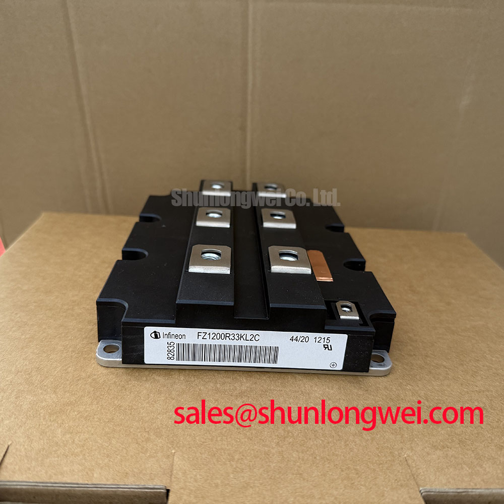
FZ1200R33KL2C-B5 Infineon 3300 V 1200 A IGBT Module
Start the service check with the converter isolated, the DC link discharged and verified de-energized, and the module terminals visually inspected for cracked housings, loosened busbar joints, or heat discoloration. The FZ1200R33KL2C-B5 is an Infineon IGBT Module with a rated collector-emitter voltage of 3300 V and a rated collector current of 1200 A under the specified datasheet conditions. Its package classification is Module. These ratings identify the component for engineering evaluation, but the permissible operating point still depends on switching conditions, thermal impedance, gate drive behavior, cooling, and the complete converter topology.
For a wind turbine full scale converter, isolate the gate driver and power circuit before making cold resistance checks. Compare the phase leg behavior with a known good channel, then inspect the gate emitter wiring, laminated busbar interfaces, clamping surfaces, and thermal path. A low resistance reading alone is not sufficient to approve the part for energization because semiconductor junctions, parallel current paths, and connected snubber networks can influence the measurement.
Transient Dynamics and Electrical Design: Optimizing Heatsink Contact Pressure on FZ1200R33KL2C-B5
Thermal interface uniformity is the first mechanical variable to control when a high current module is returned to service. The heatsink must be clean, flat within the limits defined by the mechanical design, and free from particles that could create a local pressure point beneath the module base. A thin and even thermal interface layer is preferable to a thick pool of compound. For this service procedure, a practical design consideration is a controlled TIM thickness in the range of 50 to 100 µm, provided that the selected material, heatsink surface finish, and module mounting instructions support that installation method.
Void elimination does not mean applying excessive clamping force. Excess compound can migrate toward the module edges, while insufficient coverage can leave air pockets under the active heat transfer area. Apply the material consistently across the intended contact surface, position the module without sliding it across the heatsink, and use the fixing sequence defined by the mechanical drawing. Tighten opposing screws progressively so that the baseplate is seated evenly rather than pulled down from one corner.
Sequential torque control is especially important when a replacement module is installed into an existing converter frame. The correct torque is determined by the screw size, washer arrangement, heatsink construction, thread condition, and the module manufacturer’s mechanical instructions. Do not transfer a torque value from another power module without checking those conditions. After tightening, verify that the busbar remains aligned without imposing lateral force on the terminals.
Electrical clearance should be treated as part of the transient design rather than as a cosmetic layout feature. Keep the high voltage commutation path compact, separate gate wiring from collector and emitter power paths, and avoid routing sensitive control conductors parallel to high di/dt conductors for long distances. The system engineer should verify turn off overshoot with an appropriately rated differential probe and confirm that the measured peak remains within the converter’s coordinated insulation and semiconductor limits.
When the module is used in a multi megawatt offshore or onshore wind turbine converter, enclosure airflow, salt contamination control, vibration, and service access all influence the practical thermal result. The application should be evaluated as a complete assembly rather than by the 1200 A label alone. Infineon’s IGBT Modules and Discretes Official Portfolio provides the relevant product family context for power semiconductor selection.
⚠️ Field Alert: Follow the original mechanical drawing for screw sequence and torque, and never insert or remove gate or power connectors while the converter is energized.
Benchtop Waveform Tuning: Managing Atmospheric Neutron and High Altitude Design Risks
Atmospheric neutron exposure becomes a design consideration for equipment installed at elevated sites, but a precise single event burnout failure rate cannot be inferred from the module’s voltage and current ratings. A defensible FIT assessment requires device specific radiation data, mission altitude, exposure duration, voltage stress distribution, temperature, switching duty, and the applicable reliability methodology. In service, record the installation altitude and operating profile, then submit those conditions to the equipment reliability team rather than assigning an unsupported failure number.
DC bus headroom should be assessed against the measured switching transient, not treated as a fixed percentage copied from another converter. During a controlled bench test, capture collector emitter voltage, gate emitter voltage, current commutation, and the local DC link waveform at the module terminals. The system engineer can then determine whether parasitic inductance, gate timing, busbar geometry, or an overvoltage clamp is responsible for the observed stress. Any voltage derating adopted for altitude or neutron exposure must be supported by the relevant device reliability evidence and system safety case.
Switching frequency also changes the thermal balance. A converter operating at different switching frequencies can experience materially different switching losses even when its average output power appears unchanged. Use the actual gate resistance, gate charge behavior, modulation pattern, dead time, and cooling condition in the loss model. Do not treat the 1200 A rating as a continuous current promise across every switching frequency and heatsink temperature.
High ambient operation requires airflow verification at the module and heatsink, not just a fan nameplate check. Inspect filters, duct transitions, recirculation paths, and temperature rise across the cooler. A replacement unit should be tested under the same airflow direction and enclosure condition as the original installation. If the converter uses a liquid cooled plate, confirm flow and inlet temperature as part of the equipment test plan.
Gate dead time must prevent cross conduction while avoiding unnecessary diode conduction intervals. Tune it from measured turn on and turn off behavior, driver propagation delay, temperature variation, and the selected switching strategy. Microsecond scale protection and desaturation response should be coordinated with the actual fault clearing path and the device’s specified short circuit withstand conditions. These are engineering recommendations for the converter, not published specifications of the FZ1200R33KL2C-B5.
The following comparison is useful when a repair team is checking whether a different Infineon part belongs in the same evaluation path. It is not a substitute for mechanical, electrical, thermal, and gate drive compatibility review.
| Part | Manufacturer | Category | Parameters | Evaluation point |
|---|---|---|---|---|
| FZ1200R33KL2C-B5 | Infineon | IGBT Module | 3300 V, 1200 A under specified datasheet conditions, Module package | Primary service evaluation unit |
| FS75R12KT3G | Infineon | IGBT related product | Review part specific documentation | Do not assume pin, voltage, current, or mechanical interchangeability |
The table separates a neutral comparison from a replacement recommendation. If the existing converter uses a different gate loop, terminal arrangement, or thermal interface, the service team must validate the complete interface before considering any alternate part.
Benchtop Waveform Tuning: Common Mode Transient Immunity in Harsh Industrial Environments
Common mode transient control begins with the isolation barrier and ends with the gate loop. A gate driver used with a 3300 V class power stage should be evaluated for reinforced galvanic isolation, insulation coordination, creepage and clearance, output supply behavior, and common mode transient immunity. Isolation withstand voltage and CMTI requirements must be determined for the selected driver and isolation architecture; they are not stated ratings for this IGBT module.
Spurious gate pulses can arise from common emitter inductance, driver ground movement, capacitive coupling across the isolation barrier, inadequate local decoupling, or probe connection errors. On the bench, monitor the gate emitter waveform at the module terminals rather than at the driver output alone. Compare the command signal and actual gate voltage during the fastest collector voltage transition. Any unexplained pulse should be traced through the driver supply, isolation channel, return path, and power layout before changing gate resistance.
Clearance and creepage must be preserved after the module, busbars, snubbers, and service wiring are installed. Remove sharp conductive edges near the isolation path, keep contamination away from high voltage surfaces, and ensure that cable ties or shields do not press insulation against a hot terminal. The final spacing is governed by working voltage, pollution degree, material group, altitude, and the applicable equipment standard. It is therefore a system design result rather than a universal value for this product.
For a wind converter, long cable runs between control cabinets and power stacks can increase common mode coupling. Use a defined shield termination strategy, maintain a controlled gate return, and avoid sharing the gate return with auxiliary measurement currents. The driver protection sequence should also be checked during undervoltage lockout, controller reset, emergency stop, and DC link precharge. A clean command waveform during normal operation does not prove safe behavior during every transition.
When a fault appears only at elevated DC voltage or during a rapid load change, capture the event with the same appropriately rated probe setup used for the known good phase. Check whether the event is a genuine gate disturbance or a measurement artifact. The technical discussion in Unlocking Efficiency in Industrial Drives can provide broader context for switching behavior, while the specific gate loop remains the responsibility of the converter design.
FZ1200R33KL2C-B5 Circuit Protection and Reliability: Diode Recovery and System Damping
Antiparallel diode recovery must be evaluated together with the commutation loop, load current, junction temperature, DC link condition, and gate timing. A high reverse recovery peak or a sharp recovery slope can increase voltage overshoot, electromagnetic coupling, and turn on stress in the opposing IGBT. The waveform should be measured at the module terminals with a short, controlled measurement connection so that probe inductance does not conceal or create the apparent event.
Snubber selection is a system exercise. An RC network may reduce ringing when its damping effect is matched to the actual loop impedance, but it also introduces losses and changes the thermal load. Select the network from measured ringing frequency, voltage excursion, pulse energy, repetition rate, and physical placement. The snubber must be mounted close enough to influence the commutation loop while maintaining the required insulation and service clearances.
Turn on gate resistance can also influence diode recovery stress and electromagnetic emissions. A suggested initial gate damping value may be used only as a bench tuning starting point when supported by the driver capability and the original converter design. Adjustments should be made from measured collector voltage, collector current, gate voltage, and device temperature. The final setting is system determined and should not be presented as an official parameter of the FZ1200R33KL2C-B5.
Check the desaturation or overcurrent protection path for response consistency during a controlled fault test within the device’s specified limits. The protection threshold, blanking interval, gate discharge path, and fault latch behavior must ensure that fault clearing remains within the device’s specified short circuit withstand conditions. If a thyristor gate circuit shares the same protection environment, verify its IGT, VGT, pulse width, and pulse train requirements from the thyristor documentation. A strong pulse train can improve triggering robustness in an appropriate circuit, but it must not be assumed compatible with this IGBT gate interface.
Bidirectional DC DC battery systems add repeated charge and discharge thermal cycles. Review the temperature swing at the module case, the cooling response during power reversal, the switching loss in each direction, and the mechanical stress imposed by busbar expansion. A service replacement should be assessed over the real bidirectional load profile rather than a single steady state test. Any claim about extended thermal cycling life requires an applicable manufacturer reliability report or qualified test program.
Before returning the converter to service, compare phase leg waveforms, confirm the gate driver fault response, verify thermal performance during the first controlled run, and document the measured DC link and switching peaks. The Infineon IGBT Modules Overview is an appropriate manufacturer reference for understanding the broader module product category. The FF400R12KL4C may also appear in related rectifier or front end topology evaluations, but its electrical and mechanical interfaces must be assessed independently.