Content last revised on August 28, 2026
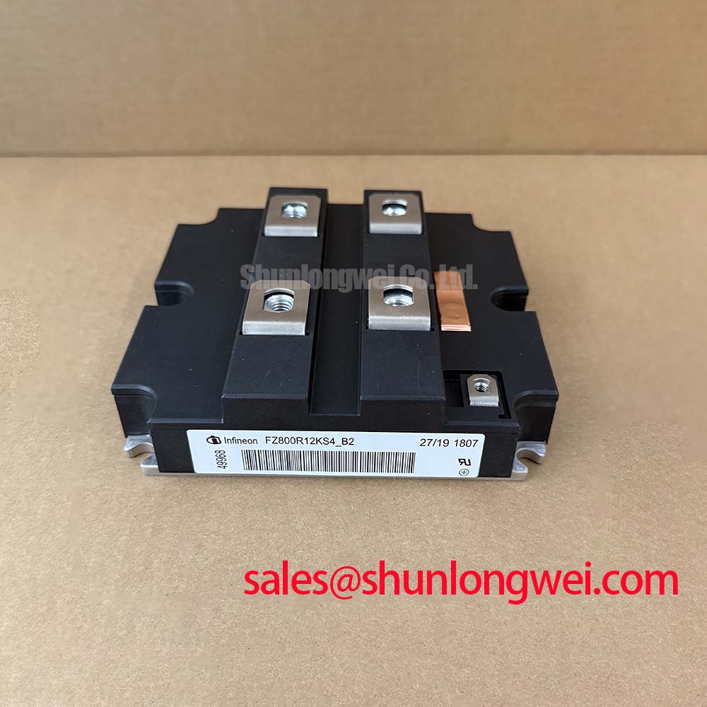
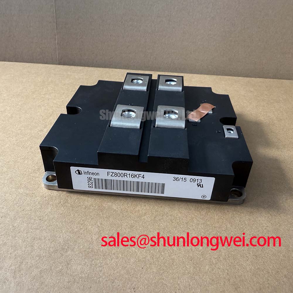
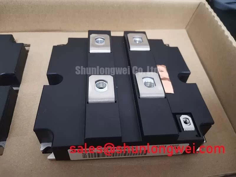
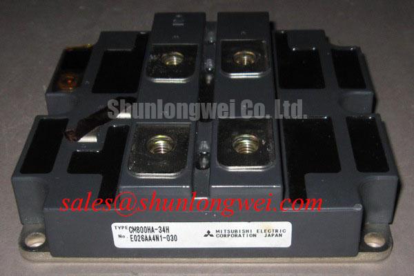
FZ800R12KF1 Infineon / EUPEC 1200V 800A Single IGBT Module
The FZ800R12KF1 from Infineon / EUPEC delivers robust power handling and exceptional thermal endurance for high-capacity industrial power converters. Featuring continuous ratings of 1200V collector-emitter voltage and 800A collector current in a single switch configuration, this module provides low conduction losses and high operational stability. It is optimized to simplify busbar structures and enhance thermal management in demanding continuous-duty applications.
Application Scenarios & Value
Solving High-Current Thermal Challenges in Heavy Industrial Drives
For 1200V high-power industrial inverters operating up to 800A continuous current, the FZ800R12KF1 single IGBT switch is the optimal choice.
Engineers often face significant thermal stress and current balance issues when designing high-power motor drives and grid-tie inverters. Operating at a collector-emitter rating of 1200V and a nominal collector current of 800A, the FZ800R12KF1 addresses these pain points by combining high power density with low saturation voltage. In heavy-duty variable frequency drives (VFDs) and utility-scale solar or wind inverters, it effectively minimizes power dissipation during continuous full-load operations.
What is the primary benefit of the low thermal resistance package in the FZ800R12KF1? It minimizes die junction temperature under extreme load, extending operating lifespan.
The single switch topology enables clean layout routing in parallel inverter legs without creating localized heat hotspots. Systems requiring lower power levels may consider the FZ800R12KE3, whereas projects demanding elevated current headroom in identical system voltages can evaluate the FZ800R12KF5. Integrating the FZ800R12KF1 into high-power conversion hardware ensures long-term reliability in harsh industrial environments.
Technical & Design Deep Dive
Optimizing Junction Thermal Path and Reverse Bias Safe Operating Area
In high-current switching modules, internal power dissipation creates steep thermal gradients across the substrate. Think of the internal thermal structure as a thermal highway: a lower thermal resistance, Rth(j-c), acts like adding lanes to relieve peak rush-hour congestion, allowing heat generated at the silicon junction to pass rapidly into the heatsink. By reducing junction thermal bottlenecks, the FZ800R12KF1 keeps die temperatures lower during high peak load transients.
Why choose a single IGBT switch topology like the FZ800R12KF1? It enables modular scalability and simplified high-current busbar layouts in mega-watt power converters.
Beyond thermal performance, switching efficiency depends heavily on gate control precision and parasitic inductance. Implementing an optimized IGBT gate drive and thermal design prevents parasitic turn-on and mitigates voltage spikes during rapid turn-off transitions. The integrated fast recovery diode provides soft reverse-recovery behavior, reducing electromagnetic interference (EMI) and snubber requirements. Furthermore, understanding thermal resistance metrics helps engineers size liquid or forced-air heatsinks accurately, preventing premature thermal trip conditions. For broad context on module architecture, review this IGBT module analysis.
Key Parameter Overview
Functional Grouping of Electrical and Thermal Ratings
| Functional Category | Key Parameter | Symbol | Value / Rating |
|---|---|---|---|
| Absolute Maximum Ratings | Collector-Emitter Voltage | VCES | 1200V |
| Continuous DC Collector Current | IC | 800A | |
| Electrical Characteristics | Collector-Emitter Saturation Voltage | VCE(sat) | 1.75V - 2.10V (typ.) |
| Gate-Emitter Peak Voltage | VGES | ±20V | |
| Thermal & Package Specs | Thermal Resistance, Junction-to-Case | Rth(j-c) | Optimized Low-Rth Substrate |
| Configuration / Topology | Circuit | Single IGBT Switch with FWD |
Frequently Asked Questions
Engineering Insights for System Integration and Operation
How does the 800A rating of the FZ800R12KF1 impact busbar design in high-power inverters?
The 800A continuous current rating requires laminated, low-inductance busbars to minimize voltage overshoots during high dI/dt switching. Using a single switch module allows engineers to design symmetrical current paths that reduce stray inductance across phase legs.
What gate driver requirements are critical for controlling the FZ800R12KF1 safely?
To drive the gate capacitance efficiently and prevent shoot-through, gate drivers should provide sufficient peak current output along with negative gate bias (typically -5V to -15V) during off-states. A active Miller clamp is also recommended to prevent parasitic turn-on.
How does VCE(sat) influence thermal dissipation in continuous duty cycles?
VCE(sat) directly determines conduction loss (Pcond = VCE(sat) × IC). A low saturation voltage reduces steady-state heat generation, allowing higher current output for a given heatsink capacity or lowering cooling system energy consumption.
Can the FZ800R12KF1 be paralleled for megawatt-class converter designs?
Yes, modules can be paralleled, but system designers must ensure balanced current sharing by matching gate drive symmetry, circuit trace lengths, and thermal mounting conditions across all paralleled devices.
What safety margins are recommended for the 1200V VCES rating in industrial systems?
For standard 400V to 690V AC line inputs, a 1200V VCES rating provides sufficient voltage margin against turn-off inductive spikes and DC bus ripple, provided snubber circuits or active clamping are utilized.
To evaluate the FZ800R12KF1 for your industrial power stage, consult detailed engineering specifications and verify mounting guidelines to maximize operational lifespan in your custom converter designs.