Content last revised on October 6, 2026
Preventing Spurious Faults: Baseplate Convexity Compensation and Screw Guidelines for GD50PGX120C6S
Inspect the module’s mounting face and heatsink contact pattern when a fault appears only after the enclosure warms up. Uneven contact can increase thermal resistance and shift operating conditions without leaving an obvious electrical fault during a cold bench test. The GD50PGX120C6S is a 1200 V, 50 A StarPower IGBT power module; those are Official Specifications, not mounting or thermal-performance guarantees.
As a Design Consideration, clean both mating surfaces, check flatness against the mechanical drawing, and spread thermal interface material thinly enough to fill surface irregularities without forming a thick insulating layer. A trial contact imprint can expose dry edges or trapped voids. If the mounting face is curved, follow the applicable mechanical drawing’s fastening sequence rather than forcing one corner flat first. Tighten mounting screws in stages with a calibrated tool to the specified fastener and heatsink requirements; do not infer a torque from the module’s current rating. Recheck nearby conductor clearance after mounting, particularly where busbars move under fastening pressure.
For incoming QA, identify the gate, collector and emitter terminals from the approved connection drawing before applying a meter. Record cold diode-mode readings in both polarities at the intended power terminals and compare them with a documented reference unit; an unexpected reading calls for a wiring and fixture check, not an immediate single-cause diagnosis. 💡 Bench Tip: Keep the gate protected from ESD while recording cold readings against a known-good reference. Any insulation test must use the test points and limits specified for the assembled equipment, with sensitive gate-drive connections handled according to its service procedure.
Field Diagnostics & Commissioning: Static and Dynamic Current Distribution in GD50PGX120C6S Topologies
Clamp current probes around each parallel branch and compare their waveforms during a controlled commissioning run if one branch heats faster than another. A matching cold diode check does not establish dynamic current sharing. As a Design Consideration, compare conductor resistance, heatsink contact and operating temperature for sustained imbalance, then inspect gate-loop symmetry and switching edges for transient imbalance. Do not assume that this model’s VCE(sat) temperature coefficient guarantees current sharing without its characteristic curves and the measured operating point.
At the gate terminals, compare turn-on and turn-off waveforms with the approved drive design. Driver source and sink capability must accommodate the switching behavior observed in the actual circuit; external gate resistance is then a bench-tuned tradeoff among ringing, switching loss and peak voltage, not a fixed value implied by the 50 A rating. Check whether Miller coupling raises the gate during opposite-device switching. An active clamp may be evaluated as a Design Consideration, but its threshold and behavior depend on the driver and module data. Likewise, use documented gate-charge and reverse-transfer-capacitance characteristics rather than assigning an unverified Cres value.
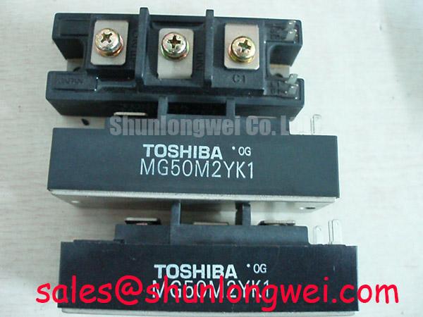
For a replacement comparison, MG200Q2YS40 is a separate module to assess against the original schematic. Ratings alone cannot establish interchangeability: compare terminal layout, switching behavior, gate-drive needs, mounting and thermal limits. In a wider converter assembly, FZ800R12KS4_B2 is another module reference for topology-level review, not an assumed rectifier stage or direct companion to GD50PGX120C6S.
GD50PGX120C6S Circuit Protection & Reliability: Calibrating Output Sinusoidal Filter vs dv/dt Reactor
Measure voltage at both the inverter output and motor terminals when a drive reports overvoltage or insulation-related faults after a cable change. Long leads can produce reflected-wave peaks through cable-to-motor impedance mismatch; their magnitude depends on rise time, cable properties, termination and operating conditions. Do not treat a possible doubled terminal voltage as a measured characteristic of GD50PGX120C6S.
As a Design Consideration, choose between a dv/dt reactor and a sinusoidal output filter using the measured motor-terminal waveform, cable arrangement, motor insulation requirements and filter losses. A reactor can soften an edge without necessarily producing a sinusoidal waveform; a sinusoidal filter needs its own compatibility and thermal checks. Maintain installation clearances to the equipment drawing and inspect filter connections before attributing repeated trips to the module. In electric forklift or warehouse traction equipment, this is a compatibility assessment only: verify the actual DC link, motor wiring and available installation space.
If the system also uses controlled rectification, examine its firing-angle strategy and input-current harmonics as system-level issues rather than GD50PGX120C6S specifications. The direct-quadrature-zero transformation explains a common framework for interpreting three-phase control signals; buck–boost converter topology provides context when reviewing a separate auxiliary supply. Neither reference establishes this module’s internal circuit. For broader device-technology context during reliability reviews, see Wide Bandgap Revolution.
GD50PGX120C6S Thermal-Electrical Optimization: High-Frequency Commutation Loop Inductance Practical Tuning
Probe collector-to-emitter voltage at turn-off and compare its peak with the measured DC-link voltage when switching faults persist despite acceptable cold checks. Stray commutation-loop inductance adds a voltage term proportional to current slew rate, so a layout that appears satisfactory at low load can show greater overshoot during a faster transition. Treat the 1200 V rating as an Official Specification; establish switching margin from measured peaks under the intended operating conditions.
As a Design Consideration, shorten and closely couple the outgoing and return current paths, then check whether planar busbar geometry keeps parallel branches comparable. Locate any snubber in the actual commutation path and select its components from measured overshoot, dissipation and resonance behavior. Recheck turn-off waveforms after each layout or gate-resistance change: damping one oscillation can alter switching loss and heatsink demand. Where a fault follows a surge event, inspect the surrounding protection circuit and allow temperature to return to the equipment’s defined test condition before repeating static measurements. No surge-current ITSM limit or junction-temperature recovery interval is asserted here for GD50PGX120C6S.