

Content last revised on October 5, 2026
Chassis Fastening and Optical Mura Checks
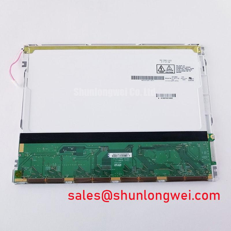
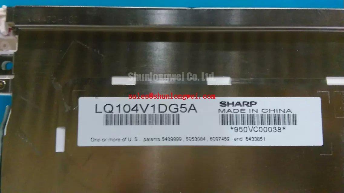
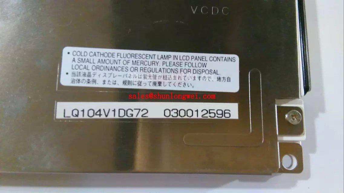
Check the label on the removed display and record its connector orientation before disconnecting the Sharp LQ104V1DG72 from the HMI assembly. The supplied product identification confirms an industrial TFT-LCD display module manufactured by Sharp (Official Factory Specification). It does not establish the module’s dimensions, supply voltage, interface pinout, backlight type, operating temperature limits, or optical ratings. Those details must be checked against the original panel documentation before a replacement is powered or fitted.
Begin a fit assessment with the removed module and its enclosure, not with the diagonal size implied by a product listing. Compare the active viewing area, outer frame, mounting points, connector clearance, cable exit, and gasket contact surfaces. A panel that enters the opening can still sit unevenly against the bezel or place a cable under strain. For the LQ104V1DG72, the installer should obtain the applicable mechanical drawing before treating any enclosure dimension as an Official Factory Specification.
Design Consideration: Uneven bezel pressure can produce a bright or dark patch that changes when the assembly is clamped. Before attributing such a patch to an electrical fault, inspect the gasket for displaced sections and check whether the chassis bears uniformly around the display. Loosen and refit the enclosure fasteners in a balanced sequence, then inspect a uniform image with the unit in its normal installed position. The appropriate fastener torque depends on the documented chassis design; a generic M3 torque value must not be presented as a Sharp limit for this module.
A cold display may also respond differently from one that has reached a stable operating temperature. If an HMI appears slow to change shades after a cold start, record the ambient conditions and compare its behavior after stabilization with the equipment’s documented acceptance criteria. Any heater, thermostat, or warm-up procedure belongs to the host equipment design. Verify its operation from the equipment schematic rather than assuming the panel has an integrated heating feature or a specified sub-zero rating.
⚠️ Maintenance Note: Inspect the enclosure gasket and ventilation path during scheduled service, and disconnect power before disturbing the display cable.
Backlight Service and Retrofit Boundaries
When the image is faint, first determine whether pixel data is present. Display a known test image and illuminate the screen at an angle while checking the host supply, display enable signal, and backlight control path against the equipment documentation. A visible image under external light can direct attention toward illumination and its driver, but it does not by itself identify which part has failed. A blank screen with no visible image calls for checks of power sequencing, signal cabling, and the controller as well.
The supplied identification does not confirm whether the LQ104V1DG72 uses a CCFL or LED backlight. The system integrator should verify the backlight architecture, electrical ratings, connector assignment, and driver requirements from the original Sharp panel documentation and the host schematic. CCFL ignition voltage, LED current, dimming range, and service-life figures from another display are not specifications for this module.
Design Consideration: A proposed lighting retrofit changes more than the light source. The technician should evaluate mechanical space, heat removal, electrical isolation, driver fault behavior, and optical uniformity in the completed display assembly. If a constant-current LED driver is being evaluated for a documented LED configuration, its open-load and short-load responses should be checked under the intended operating conditions. PWM dimming should likewise be assessed for visible flicker and interference in the host equipment; its frequency and operating range are system-design decisions, not inferred panel ratings.
For repair planning, retain the distinction between a backlight repair and a panel substitution. A display such as LMS700KF01-001 can be reviewed as a separate sourcing candidate, but its fit, interface, optical performance, and electrical requirements must be compared with the original equipment records before anyone treats it as interchangeable with the LQ104V1DG72.
Thermal Cycling, Polarizer Condition, and Gasket Integrity
Inspect the screen in both its powered and unpowered states when evaluating a display that has experienced repeated temperature changes. Look for persistent cloudy regions, edge discoloration, lifting around the viewing area, and marks that remain fixed as the image changes. Record where each feature appears relative to the bezel and gasket. That record helps separate an optical symptom from pressure introduced by the enclosure, although visual inspection alone cannot establish the condition of internal adhesives or seals.
Design Consideration: Temperature changes can alter display response and can expose weaknesses in an enclosure’s moisture control. Check for condensation on accessible surfaces after a cold-to-warm transition, examine the gasket for gaps or compression irregularities, and verify that the host enclosure’s sealing and ventilation arrangements match its maintenance instructions. Do not infer a LQ104V1DG72 thermal-cycle range, sunlight contrast rating, or protective coating from its industrial product category.
A marine radar or navigation bridge console is one possible compatibility assessment, not an established application rating for this panel. For that equipment, the integrator should verify the documented viewing conditions, enclosure sealing, optical readability, and environmental requirements at assembly level. Salt exposure or direct sunlight performance cannot be assigned to the bare display module without relevant specifications and system-level evaluation. For broader context on viewing characteristics and display integration, see The Ultimate Guide to Industrial TFT LCD Technology.
Localizing a Single Vertical Hairline Defect
Run the host’s known-good image source through solid red, green, and blue screens, followed by a uniform dark image. Note whether a hairline remains in the same column, changes color, disappears on a particular test image, or moves when the input image changes. Photograph the defect with the bezel installed, then repeat the observation only if the equipment’s service procedure permits safe access. This comparison creates a useful fault record without assigning a single cause to the line.
A fixed vertical line can justify closer examination of the signal path, panel connection, and display assembly. Check that the cable is fully seated and that its routing has not placed tension on the connector. Compare the host output with a known-good signal path where test access exists. Avoid pressing on the glass or assuming that a line identifies a particular internal driver or bond failure; the supplied product information does not document the module’s internal construction.
For a dark region rather than a colored line, use angled external light to check whether image content is still being formed. If content is visible, continue with the documented backlight and driver checks. If it is not, measure the relevant supplies and control signals using the original service information before condemning the panel. The disposition of the LQ104V1DG72 should follow those measurements and the equipment’s acceptance criteria, not an assumed backlight lifetime or an unverified optical threshold.