

Content last revised on October 14, 2026
M50100TB200 Module Identification and Replacement Checks
- Isolate the equipment supply, discharge stored energy, and verify absence of voltage before accessing the M50100TB200 terminals.
- Record terminal markings and compare the installed connections with the equipment schematic before disconnecting conductors.
- Inspect the mounting surface, terminal hardware, and thermal interface for looseness, contamination, or uneven contact.
- Record the semiconductor fuse designation and protection components before evaluating a replacement module.
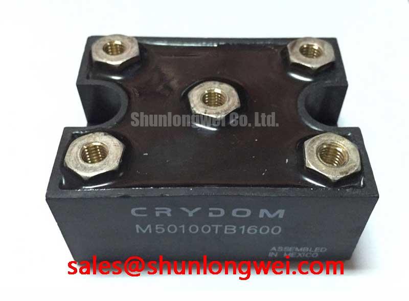
The M50100TB200 is identified here as a SanRex / Crydom diode/thyristor module with an Isolated Power Module package description. Confirm its current rating and associated operating conditions from the manufacturer’s datasheet before selecting a replacement. Replacement assessment should keep the module, its protection network, and its mounting arrangement together rather than treating the current marking as a complete compatibility specification.
| Product attribute | Supplied specification |
|---|---|
| Model | M50100TB200 |
| Brand designation | SanRex / Crydom |
| Product category | Diode/Thyristor Module |
| Rated current | Consult the manufacturer’s datasheet for the rating and applicable operating conditions |
| Package | Isolated Power Module |
| Blocking voltage | Consult the manufacturer’s datasheet |
| Protection and assembly limits | Consult datasheet for circuit configuration, terminal assignments, surge withstand, thermal resistance, and tightening torque |
Benchtop Waveform Tuning: Mitigating Stress via Semiconductor Protection Fuse Selection on M50100TB200
Compare the fuse’s total clearing I²t with the semiconductor’s permitted surge I²t at matching test conditions before accepting the protection arrangement. Design Consideration: fuse coordination depends on prospective fault current, applied voltage, initial junction temperature, and fault duration. The fuse’s pre-arcing value alone does not represent all the energy passed during interruption, and coordination does not guarantee damage-free operation during every short circuit.
Build the coordination record around the actual fuse designation and module limits. Capture total clearing I²t, peak let-through current, interrupting capacity, and the semiconductor surge-current test conditions. Check the contribution of stored energy and fault paths that bypass the fuse. A suitably rated fuse still needs an installation capable of interrupting the available fault current safely.
For bench evaluation, observe module terminal voltage and current during controlled operation using appropriately rated instrumentation. Deliberate short-circuit testing belongs in a suitably equipped protection-test facility, not an ordinary repair bench. Unexpected current peaks should prompt examination of firing timing, commutation conditions, and connections rather than an immediate increase in fuse rating.
During replacement assessment, M50100TB1600-8699 is a related comparison candidate, not an established interchangeable part. Compare circuit arrangement, blocking capability, surge withstand, terminal layout, and mounting dimensions before approving substitution; a similar model designation does not establish equivalence.
Assembly Integrity & Layout Architecture: Implementing Surge Energy Dissipation and Voltage Clamping for M50100TB200
Trace the surge-current path from the input terminals through the protective network before selecting a MOV or changing an RC snubber. Design Consideration: protection must limit semiconductor terminal stress while accommodating normal supply variation, temporary overvoltage, and the applicable surge environment. IEC 61000-4-5 addresses surge immunity testing; it does not establish a standalone immunity certification for this module.
MOV selection should account for continuous operating voltage, clamping behavior at the relevant surge current, energy duty, and end-of-life protection. Snubber selection should account for transient damping, capacitor pulse capability, resistor dissipation, and the effect on commutation. Component values remain system-dependent and should be validated at the module terminals, where wiring inductance can alter the measured stress.
Design Consideration: Keep the protection-current loop compact to reduce inductive overshoot, then verify terminal-voltage peaks under the equipment’s applicable switching and surge conditions. Where the circuit includes thyristor triggering, evaluate the gate path against its actual trigger and immunity limits rather than importing IGBT dead-time, Miller-clamp, or Kelvin-emitter prescriptions.
When reviewing the supply-side schematic, the M505013F can be examined as a separate power-stage component, with its role established from its own circuit documentation. The Shindengen Power Semiconductor Modules & Diodes resource provides broader semiconductor context, not model-specific ratings for the M50100TB200.
Benchtop Waveform Tuning: Evaluating Thermal Resistance and Mounting on M50100TB200
Check heatsink flatness and module seating before interpreting a rising case temperature as an electrical fault. Design Consideration: junction-to-case thermal resistance describes the semiconductor heat path under defined conditions; interface and heatsink resistance add separate temperature rises. Neither the baseplate material nor a numerical thermal resistance should be inferred from the package description.
Apply the specified thermal-interface material using the approved assembly method, and tighten mounting hardware to the applicable documented torque and sequence. Check for uneven seating or housing distortion. Terminal tightening and mounting tightening serve different purposes and should not be treated as interchangeable instructions.
During a controlled load test, record current waveform, case temperature, heatsink temperature, and cooling conditions. Correlate abnormal heating with conduction losses, connection resistance, and interface condition. The Field Engineer’s Handbook offers supplementary troubleshooting guidance for organizing those observations.
For a grid-tied static var compensator or thyristor-switched capacitor assembly, evaluate compatibility against the actual branch circuit, capacitor switching duty, insulation requirements, and cooling arrangement. Approve integration only after the electrical connections, protection coordination, and thermal operating conditions match the equipment requirements.