

Content last revised on October 12, 2026
MDS200-16 Thermal-Electrical Optimization: High-Current DC Rectifier Topologies for Practical Tuning
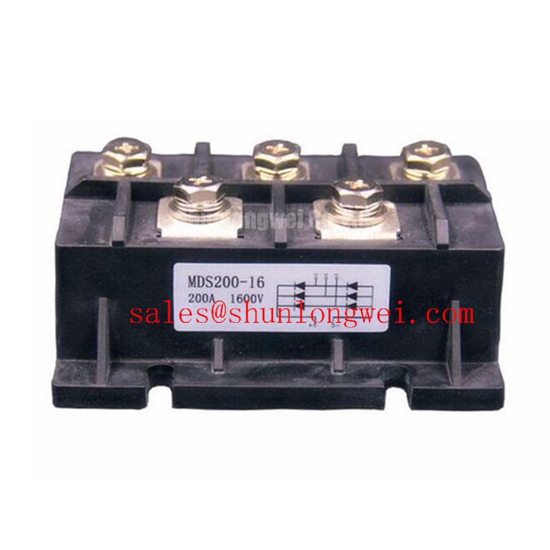
MDS200-16 | Manufacturer: SanRex (Sansha Electric) | Product: Bridge Rectifier Module | Official Specification: 1600 V, 200 A | Package: Three-Phase Rectifier Case | Consult Datasheet: rating conditions, terminal drawing, surge and recovery characteristics, fuse coordination, and mounting torque.
I trace the isolated transformer secondary connections and DC bus polarity before assessing an MDS200-16 replacement. Terminal locations must match the module connection drawing, not merely the position of the existing cables. Disconnect the supply, verify DC-link discharge, and separate parallel paths before making cold-state diode measurements; connected capacitors and adjacent bridges can otherwise obscure the results.
As a Design Consideration, a six-pulse rectifier uses a three-phase bridge, while a twelve-pulse arrangement combines bridges supplied by appropriately phase-shifted transformer secondaries. Where the system uses an interphase transformer to combine parallel bridge outputs, current sharing depends on transformer characteristics, branch impedance, and connection symmetry. A kiloampere-level system requires an independently qualified multi-branch architecture; the module’s 200 A rating does not establish that system capability.
Measure each bridge branch under the same load condition and compare terminal temperatures with the corresponding current readings. Unequal heating may warrant checking contact resistance, cooling distribution, transformer balance, and interphase-transformer operation. For measurement-circuit background, TI Current Sense Amplifiers and Shunt Monitors explains sensing options; isolation and common-mode requirements remain properties of the complete measurement design.
During mechanical integration, inspect heatsink flatness, mounting-hole alignment, terminal support, and the thermal-interface installation procedure. Apply the manufacturer’s separate mounting and terminal torque requirements rather than transferring values from another case style. Cable strain should not be carried by the module terminals. Assess external creepage and clearance against the equipment’s working voltage, pollution conditions, and applicable insulation requirements rather than treating the 1600 V device rating as an assembly insulation approval.
For sourcing comparisons, MDS300A1600V is a separate candidate requiring comparison of circuit configuration, rating conditions, terminal geometry, and thermal performance. Engineers may evaluate the MDS200-16 for a high-current green hydrogen electrolyzer DC power rectifier, subject to those system compatibility checks; neither the application nor another part number establishes interchangeability.
Preventing Spurious Faults: Minimizing Commutation Turn-Off Voltage Guidelines for MDS200-16
Capture voltage across the commutating diode path together with branch current to distinguish rectifier transients from measurement pickup. Use probes and isolation arrangements suitable for the circuit potential, and compare events at equivalent load and temperature conditions. A disturbance coinciding with commutation can involve recovery current, wiring inductance, transformer leakage, or downstream switching activity.
As a Design Consideration, reverse-recovery peak current and recovery duration depend on the preceding forward current, junction temperature, reverse bias, and imposed current slope. Recovery time alone does not establish soft-recovery behavior; the waveform shape and test conditions matter. Treat these characteristics as part-specific comparison criteria rather than assigning fast-recovery performance to the MDS200-16 from its voltage and current ratings.
Engineering Recommendation: Keep corresponding rectifier branch connections geometrically balanced to reduce unequal parasitic impedance, then validate current sharing and commutation voltage peaks under representative operating conditions.
The MDS300-16 can enter a separate rectifier-stage assessment where another branch or power assembly requires evaluation, but adding or combining modules requires system-level qualification. DC-link capacitance also changes ripple-current paths and charging demand. The reference Film Capacitors in High Ripple Current DC-Link Applications provides general capacitor background, not an MDS200-16 capacitor-selection prescription.
This bridge rectifier has no IGBT gate-drive function. Gate dead time, Miller suppression, negative gate bias, and desaturation shutdown belong to any separately installed controlled switching stage, not to the rectifier’s terminal interface.
Preventing Spurious Faults: ITSM Safety Derating for Repetitive Events Guidelines for MDS200-16
Compare the recorded startup or fault-current waveform with the surge specification’s pulse shape, initial temperature, and reverse-voltage conditions before judging protection adequacy. If the applicable surge test specifies a sinusoidal 10 ms half-cycle, that condition is a comparison boundary, not permission for repeated overload operation.
As a Design Consideration, fuse coordination should compare the fuse’s total clearing I2t at the relevant circuit voltage with the semiconductor’s applicable withstand conditions. Record prospective fault current, fuse type, clearing characteristics, and device temperature together. Pre-arcing I2t alone omits the arcing interval and is insufficient for a complete coordination decision.
Repeated charging events require assessment of the actual current history and cooling intervals. Review case-temperature measurements alongside the thermal model when evaluating junction-temperature margin and subsequent reverse-voltage reapplication. Future of Power Electronics offers broader technology context, not a surge-test standard. Close the protection assessment by checking the selected fuse, startup control, and rectifier temperature against the same documented operating conditions.