Content last revised on October 17, 2026
Optical Luminance Degradation Curve & CCFL-to-LED Modernization Retrofit Pathways
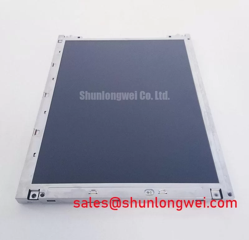
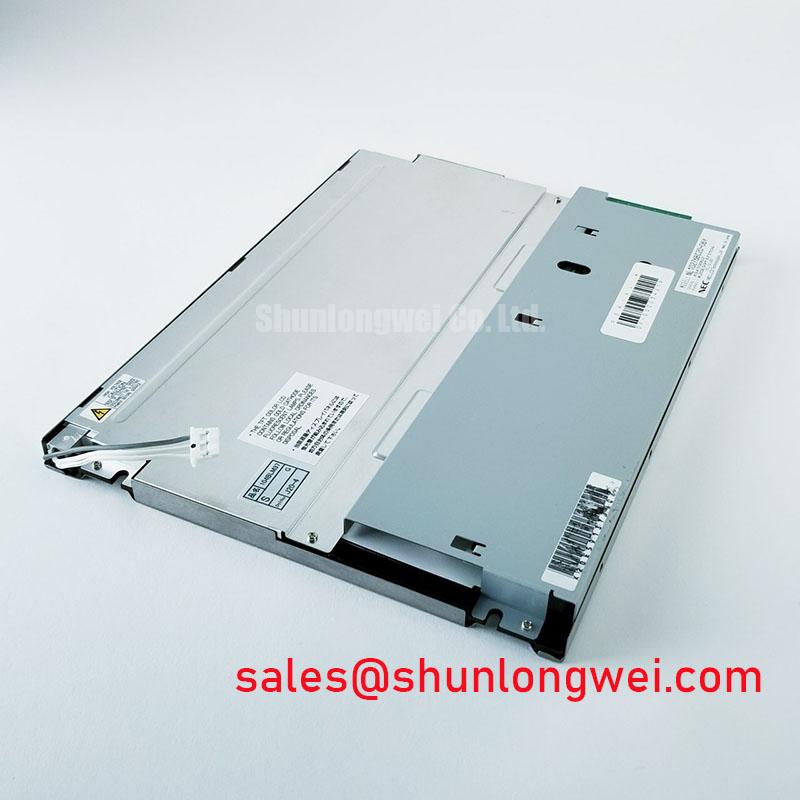
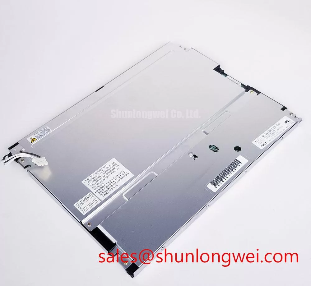
With the equipment isolated, inspect the display cable seating and backlight connections before attributing a dark operator screen to panel failure. The NEC NL10276BC30-17B is a TFT-LCD active-matrix color display module in the industrial LCD/HMI category. Separate loss of illumination from loss of image data: under suitable external illumination, a faint image can help direct attention toward the backlight circuit, although it does not establish the failed component.
For replacement assessment, record the complete panel designation, connector orientation, mounting arrangement, and installed controller configuration. Electrical ratings, optical specifications, interface assignments, and mechanical dimensions require the model-specific datasheet; the model designation alone is not a wiring specification. Field Alert: Disconnect equipment power and allow the associated power circuits to discharge before reseating display or backlight connectors.
Compare center and edge brightness using the same image, viewing position, ambient lighting, and brightness command before deciding whether illumination has deteriorated. As a Design Consideration, measurements taken under different conditions cannot establish a meaningful degradation curve. Record the operating state alongside each observation so that a controller setting change is not mistaken for optical aging.
A dark region, intermittent illumination, or audible noise warrants inspection of the installed backlight power path, connector condition, and driver behavior. These symptoms can have several causes. Correlate brightness changes with the driver input supply and enable signal, using suitable instruments and the equipment service procedure. A stable image with unstable illumination directs a different investigation from image corruption accompanied by steady illumination.
A CCFL-to-LED conversion is a system modification, not an established feature or approved upgrade of the NL10276BC30-17B. As an Engineering Recommendation, evaluate any proposed conversion against the original optical geometry, driver interface, thermal path, and enclosure clearances. Lamp ignition requirements must come from the installed lamp and inverter documentation; LED drive current and dimming behavior must come from the replacement assembly specification.
Assess contrast in the actual enclosure, including cover-window reflections and operator viewing direction. Anti-glare treatments and optical bonding change the complete optical stack and require separate compatibility assessment. The manufacturer’s broader industrial TFT display information provides technology context, but does not establish sunlight readability, viewing-angle technology, or retrofit approval for this panel.
Wide Temperature Operational Margin & Sub-Zero Liquid Crystal Viscosity
Compare cold-start image behavior with stabilized operation before changing controller timing to compensate for sluggish transitions. As a Design Consideration, liquid-crystal response generally slows as temperature falls, while illumination and power-conversion behavior can also change. Separate persistent image trails from unstable synchronization by observing a repeatable moving pattern and a stationary reference image.
Thermal assessment must stay within the panel’s documented operating and storage limits. An enclosure temperature target is not a panel rating, and storage tolerance does not establish powered-operation capability. Measure conditions near the installed display rather than relying only on cabinet inlet temperature, particularly where adjacent electronics or restricted airflow create local heating.
For interface troubleshooting, identify the actual signal standard from the connector assignment and controller schematic. Then examine clock quality, data timing, and supply stability at the receiving end under the relevant operating conditions. As an Engineering Recommendation, compare captured waveforms with the receiver requirements and a known-good signal path; cable continuity alone does not establish adequate timing margin.
Check startup and shutdown sequencing against the panel and controller requirements when investigating temporary white screens or residual images. Observe the relationship between logic power, valid image data, and backlight enable rather than imposing a generic delay. For enclosure-level thermal and environmental assessment, Industrial Display & HMI Solutions offers additional integration context; sealing and condensation control remain properties of the completed assembly.
Constant Luminance Output Control & L70/B50 LED Lumen-Maintenance Verification
Hold the commanded brightness steady while observing illumination after thermal stabilization. As a Design Consideration, brightness drift can involve the light source, its driver, supply variation, or temperature-dependent optical behavior. Compare the electrical command with measured light output before treating an apparent brightness change as evidence of panel aging.
Automatic brightness compensation should be assessed as part of the installed control system, not assumed to exist inside the NEC NL10276BC30-17B. Increasing drive to recover brightness can change thermal loading. Any compensation strategy therefore needs validation against the applicable light-source and driver limits, with measurements made in the closed equipment enclosure.
L70 describes a lumen-maintenance threshold, while B50 identifies a population fraction associated with a defined assessment. Neither term is interchangeable with MTBF or a half-brightness lifetime. Such claims require a stated test method, operating conditions, and applicable source data; they are not established specifications for this panel here.
During a separately qualified LED retrofit, assess dimming across the equipment’s usable adjustment range. As an Engineering Recommendation, examine light-output stability, flicker, acoustic behavior, and driver heating together, leaving switching frequency and control limits to the selected driver and system validation. Manufacturer background available through NEC should not be interpreted as a panel-specific lifetime declaration.
Industrial Bezel Mechanical Envelope Tolerances & Mounting Screw Torque Optimization
Check the mounting points, bezel opening, connector access, and cable exit against the installed assembly before tightening the panel into place. As a Design Consideration, uneven support or bezel pressure can contribute to visible nonuniformity. Compare a uniform test image before and after installation to identify changes associated with mounting stress.
Use the fastening requirements for the actual panel and supporting chassis rather than applying a generic screw-size torque. Confirm thread engagement and clearance behind each mounting point. Tightening should maintain even support without forcing the module to correct a distorted bracket; the assembly drawing and approved installation procedure determine the final fastening method.
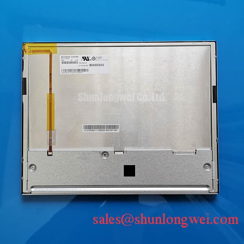
When evaluating replacement material for a CNC operator panel or robot teach pendant, compare mechanical fit, image format, electrical interface, backlight requirements, and controller compatibility independently. The NEC NL8060BC31-32 can be included in a documented comparison, but it is not established here as a compatible substitute for the NL10276BC30-17B. Similar naming does not establish interchangeability.
If optical bonding or an additional protective window is proposed, assess adhesive compatibility, assembly stress, reflections, and service access at the enclosure level. After reassembly, check uniform dark and light fields, text clarity, brightness adjustment, and cable movement through the equipment’s normal travel. Investigate installation-dependent changes before returning the display assembly to operation.