
Content last revised on September 29, 2026
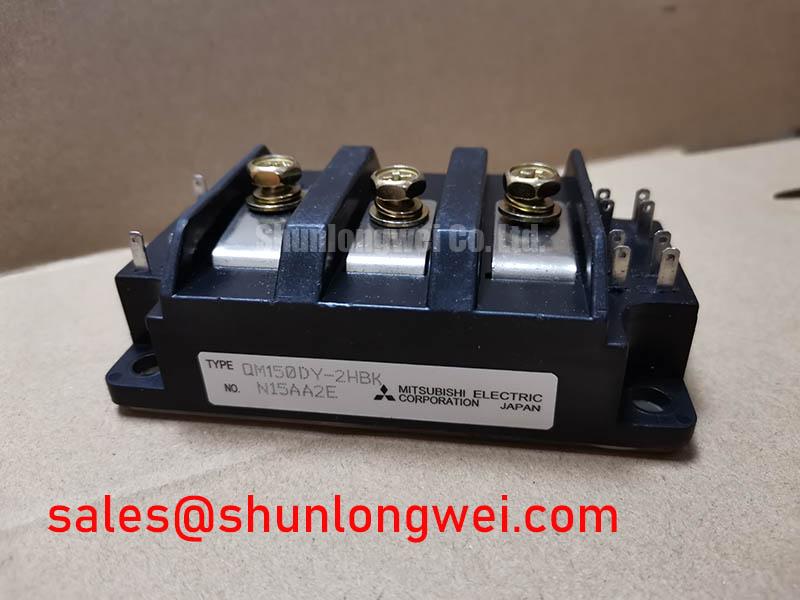
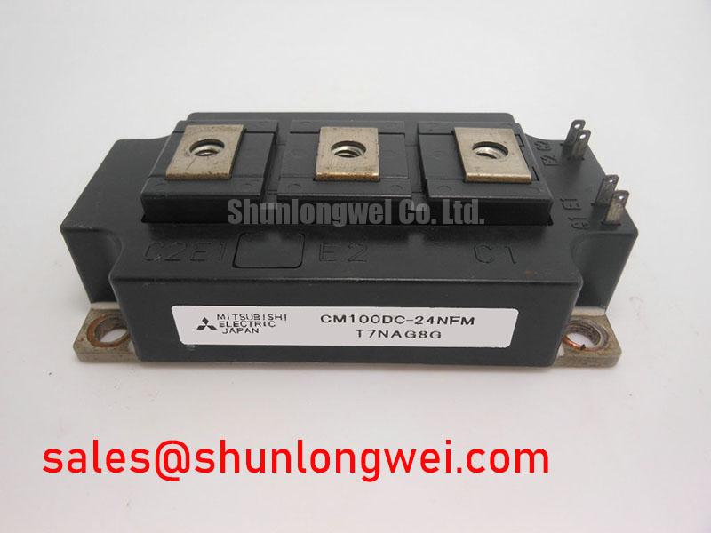
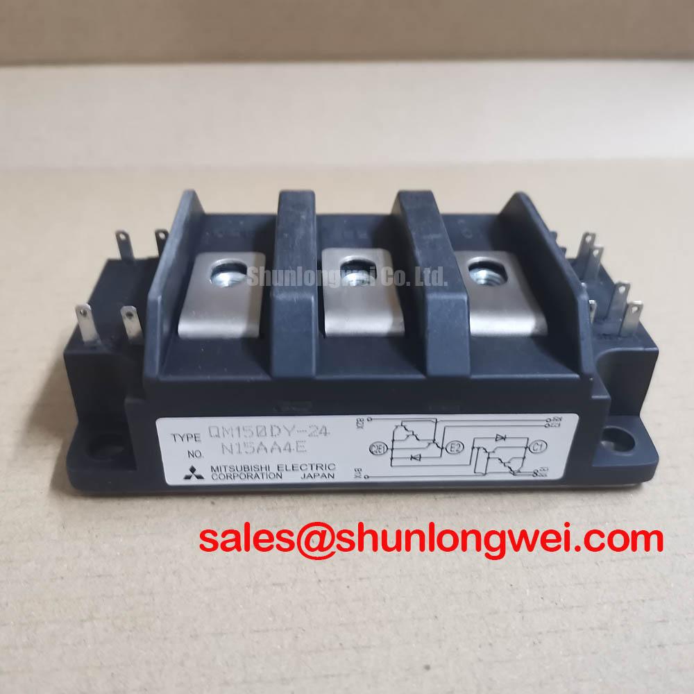
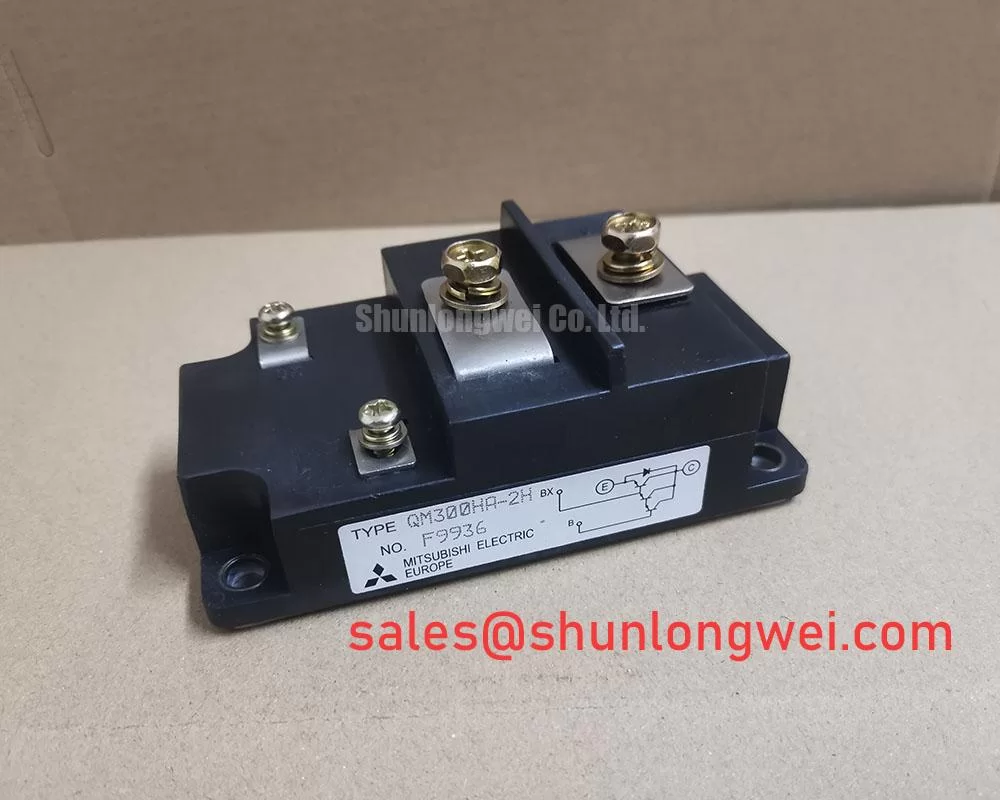
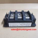
Mitsubishi Electric QM150DY-24 and QM300HA-2H 1200V 150A and 1000V 300A IGBT Power Modules
Before energizing a replacement, inspect the module body and terminals, then verify the nameplate ratings against the drive circuit and measure the unpowered power terminals for unexpected low impedance. The QM150DY-24 and QM300HA-2H are Mitsubishi Electric IGBT power modules intended for evaluation in industrial power conversion equipment, including electric material handling and forklift traction systems.
| Parameter | QM150DY-24 | QM300HA-2H |
|---|---|---|
| Type | Dual IGBT Module | Single IGBT Module |
| Collector Emitter Voltage, VCES | 1200 V | 1000 V |
| Collector Current, IC | 150 A | 300 A |
| Power Dissipation, PD | 780 W | 1660 W |
| Isolation Voltage | 2500 V | 2500 V |
| Operating Junction Temperature | −40°C to 150°C | −40°C to 150°C |
| Configuration | 2-Pack | Single |
The values in this table are official product specifications supplied for this comparison. Gate drive voltage, switching frequency, short circuit withstand time, thermal resistance, transient thermal impedance, reverse recovery characteristics, and terminal layout should be confirmed from the applicable Mitsubishi Electric documentation before circuit approval.
QM150DY-24 and QM300HA-2H Thermal Electrical Optimization for Braking Choppers
For a regenerative braking chopper, the IGBT and ballast resistor must absorb deceleration energy without exceeding the DC link, semiconductor current, resistor pulse, or thermal limits. The QM150DY-24 uses a dual IGBT configuration, while the QM300HA-2H is specified as a single IGBT module. The choice between them depends on the original topology, gate-drive channels, current sharing arrangement, and available heatsink interface rather than current rating alone.
As a Design Consideration, engineers should calculate braking energy from the motor and load profile, then compare the resulting pulse duty with the resistor manufacturer’s short-time and repetitive ratings. Check the chopper collector voltage during the complete switching event with a suitably rated differential probe. If the measured waveform approaches the device voltage boundary, review commutation loop inductance, resistor wiring, snubber strategy, and control timing before increasing the braking duty.
Thermal inspection should include heatsink airflow, dust accumulation, mounting flatness, and the condition of the thermal interface material. A maintenance program should monitor contact temperature under a repeatable load and investigate any gradual increase rather than relying only on protection trips. ⚠️ Maintenance Note: Isolate the DC link and allow the specified discharge process to finish before touching terminals or removing the module.
Output Filter and dv/dt Reactor Coordination
Long motor cables can behave as transmission lines, and impedance mismatch may create reflected switching edges that produce high terminal stress. A commonly discussed worst case is a terminal spike approaching twice the DC-link voltage, but the actual waveform depends on cable length, motor impedance, switching speed, termination, and measurement technique; it is not an official rating of either module. Designers should verify peak collector-emitter voltage directly at the module and motor terminals during representative switching tests.
Sinusoidal filters, dv/dt reactors, and common-mode components perform different functions. A sinusoidal filter changes the motor-side waveform substantially, while a dv/dt reactor limits edge steepness without necessarily producing a sinusoidal output. Selection is therefore system-determined. The gate driver must source and sink the required peak current for the selected gate charge and switching profile, while external gate resistance can be tuned as a Typical Starting Point during bench testing. Any damping value must be validated against switching loss, ringing, cross conduction, and thermal rise.
The drive supply and protection arrangement should also be checked against associated components such as the QM100HY-2H when that device is present in the same power topology. This reference does not establish electrical interchangeability.
Fault Clearing and Short Circuit Protection Boundaries
Desaturation protection, current sensing, gate shutdown, and DC-link protection must be reviewed as one coordinated fault-clearing system. Type I and Type II short circuit behavior, including any sub-10-microsecond detection claim, requires the applicable manufacturer test conditions and is not included in the supplied specifications for these two modules. Engineers should not transfer a protection delay from another IGBT family without checking short-circuit safe operating area and gate-driver response.
A two-stage soft turn-off approach may reduce inductive overshoot during a fault, but its timing and gate-current profile are system design variables. Keep the driver return path and power commutation loop compact, separate high-current paths from sensitive protection traces, and verify the collector-emitter waveform at the module pins. A fault that appears intermittent may involve wiring inductance, probe connection, gate supply behavior, current-sensor saturation, or nuisance protection thresholds; compare captured waveforms with a known-good operating cycle rather than assigning a single cause.
Transient Thermal Impedance Evaluation Under Pulsed Load
The official power dissipation values are 780 W for QM150DY-24 and 1660 W for QM300HA-2H, but these figures do not by themselves determine allowable repetitive pulse operation. Junction temperature evaluation requires the applicable case-temperature condition, steady-state thermal resistance, transient thermal impedance curve, switching loss, conduction loss, pulse duration, duty cycle, and heatsink performance.
As an Engineering Calculation, a multi-RC thermal model can represent the junction-to-case response by applying each pulse loss through the manufacturer’s transient thermal impedance data, then adding the measured case temperature. The resulting peak junction estimate must remain within the official −40°C to 150°C operating junction range under the tested duty profile. If the required curve is unavailable, do not substitute a generic module curve.
Check heatsink contact pressure, interface material coverage, mounting flatness, and airflow direction during service. For high-altitude installations or applications exposed to cosmic-ray-related single-event effects, FIT, SEB, and derating conclusions require application-specific evidence; no such reliability figures are provided here. Thermal layout practices can be reviewed alongside The Advanced Thermal Management Revolution. For forced-air systems, Computational Fluid Dynamics for Forced Air Heat Sinks can support airflow investigation, but the final result should be confirmed through temperature measurement on the assembled equipment. A neutral comparison point for related system evaluation is QM200HA-HK, subject to independent specification matching.