Content last revised on April 30, 2026
RM10TA-H Mitsubishi Rectifier: 800V 20A 3-Phase Bridge Module Analysis
Why do engineers specify a dedicated 800V rectifier block rather than discrete diodes for 400V-class industrial inverters? The RM10TA-H delivers a stress-resilient 3-phase rectification front-end, leveraging an electrically isolated baseplate to strictly optimize thermal impedance control and system-level mounting density. Why choose the RM10TA-H module? It simplifies power layouts and enhances reliability by integrating six diodes on an isolated baseplate. Boasting a 800V VRRM, a 20A IO rating, and an insulated package, it minimizes assembly time and eliminates complex busbar layouts. By providing a sufficient reverse voltage margin, it operates flawlessly during AC line surges without risking premature avalanche breakdown. For compact AC motor drives prioritizing thermal margin and structural simplicity, this 800V 20A module is the optimal choice.
FAQ
Solving Core Engineering Dilemmas with the RM10TA-H
- How does the insulated baseplate of the RM10TA-H simplify thermal design?
By providing electrical isolation up to a high withstand voltage, it allows engineers to mount the rectifier directly onto the same grounded heatsink as the active inverter stage. This drastically reduces the overall physical footprint and eliminates the need for external insulating pads that inherently degrade thermal resistance. - Is the 800V peak repetitive reverse voltage (VRRM) sufficient for standard 400V AC networks?
Yes. Operating on a 480V RMS line yields a peak voltage of approximately 678V. The 800V rating offers an adequate safety margin for routine line fluctuations, reliably maintaining the device within its Safe Operating Area during normal grid transients. - What is the primary advantage of its integrated 3-phase configuration over discrete components?
It fundamentally reduces stray inductance and minimizes assembly points, thereby eliminating the solder fatigue risks associated with multi-device layouts and enhancing overall system reliability.
Key Parameter Overview
Highlighted Specifications for Precision Drive Designs
Understanding the exact parameters of the RM10TA-H is critical for precise system integration.
| Key Parameter | Value | Engineering Implication |
|---|---|---|
| VRRM (Repetitive Peak Reverse Voltage) | 800V | Provides robust blocking capability for 400V-class AC lines, minimizing overvoltage breakdown risks. |
| IO (Maximum Output Current) | 20A | Supports continuous medium-power loads without excessive thermal stress. |
| Configuration | 3-Phase Bridge | Streamlines front-end rectification, drastically reducing parasitic inductance. |
| Isolation | Insulated Baseplate | Enables unified heatsink mounting alongside active switching modules. |
Download the RM10TA-H datasheet for detailed specifications and performance curves.
Technical Deep Dive
Architectural Integrity: Thermal Interface and Electrical Isolation
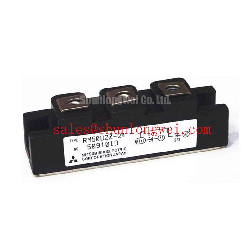
At the core of the Mitsubishi RM10TA-H is its refined electromechanical architecture. The module securely houses six rectifying diodes mounted on a highly conductive alumina substrate. Think of this insulated substrate as a thermal superhighway with a built-in toll booth—it freely permits heat traffic to pass through to the heatsink while strictly blocking any dangerous electrical current from crossing the barrier. This ensures optimal thermal management without compromising user safety or circuit isolation.
Furthermore, the physical integration into a single housing completely changes the dynamic of power circuit routing. The 3-phase integrated bridge acts like a pre-assembled manifold in a high-pressure hydraulic system. Instead of piping six individual check valves (discrete diodes) and risking leaks—which in power electronics translates to parasitic inductance and unwanted electrical resistance—the manifold provides a single, optimized flow path for the incoming AC power. This structural rigidity protects the silicon wafers from the micro-vibrations and thermal expansion mismatches that frequently plague discrete component arrays over long operational lifespans.
Application Scenarios & Value
Achieving System-Level Benefits in AC Motor Inverters
Engineers consistently face stringent layout constraints when designing the front-end of an industrial motor drive. Specifically, when the massive DC link capacitor bank is initially energized from the main grid, the system draws a substantial transient load. During this initial charging phase, the rectifier must endure a massive current surge. The robust surge forward current capability of the RM10TA-H guarantees that the silicon junction does not reach destructive temperatures during this critical millisecond window.
By pairing this rectifier with an appropriately sized inrush current limiter, designers seamlessly ensure compliance with strict IEC 61800-3 EMC directives while safeguarding the diode junctions. While the RM10TA-H perfectly addresses 20A, 400V-class requirements, systems demanding higher load capacities can effortlessly step up to the RM50TC-2H, which scales the architecture to 50A and 1600V. Alternatively, for slightly varied footprint requirements in the 25A spectrum, the SKD 25/02 presents a formidable alternative. Ultimately, standardizing on a robust rectification tier like the RM10TA-H transcends basic component selection; it establishes a strategic foundation for scalable, high-efficiency power architectures capable of meeting next-generation industrial demands.