

Content last revised on October 6, 2026
Benchtop Waveform Tuning: DC-Link Layout and Switching Stress on SKIIP32NAB12
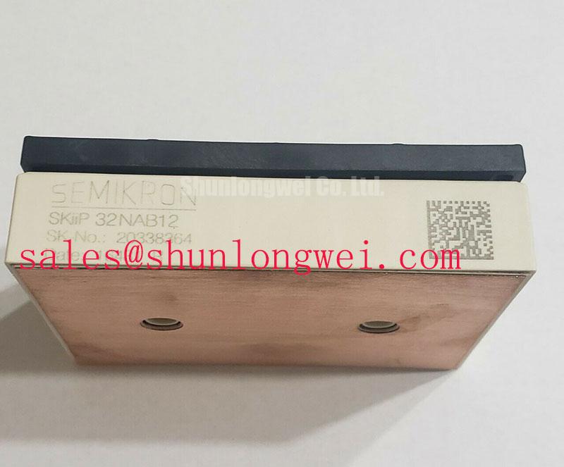
With the DC link discharged and verified safe, compare the replacement assembly’s terminal connections with the equipment schematic before mounting SKIIP32NAB12. Semikron specifies an inverter IGBT collector-emitter voltage rating of 1200 V and a rectifier diode repetitive peak reverse voltage rating of 1600 V (Official Datasheet Specifications). These are device ratings, not permissible DC-link operating voltages: switching overshoot and the equipment’s operating conditions must be assessed separately.
When commissioning the drive, place a suitable differential probe across the switching terminals and inspect turn-off peaks under representative load conditions. As an Engineering Calculation, the peak voltage includes the DC-link voltage plus an inductive contribution that rises with loop inductance and current slew rate. A compact, closely coupled DC-link connection can reduce that contribution, but its geometry and clearances must be validated against the host equipment’s insulation and mechanical requirements. If a snubber is being evaluated, select and test it against measured waveforms rather than treating a capacitor value from another drive as a module specification.
For maintenance planning, compare switching captures after DC-link capacitor or busbar work with the machine’s known-good records. A change in overshoot may warrant inspection of connection integrity, capacitor condition, or gate-drive behavior; the waveform alone does not establish a single cause. Semikron’s MiniSKiiP power-module information provides broader product-line context, while the original equipment documentation remains necessary to establish this assembly’s mounting and circuit details.
Field Diagnostics and Commissioning: Braking Chopper Operation
The SKIIP32NAB12 brake chopper has a specified collector current of 20 A at 80 °C (Official Datasheet Specification). During deceleration, record DC-link voltage, chopper command, and current through the installed braking path. If the link rises unexpectedly, compare those traces with the controller’s braking sequence and inspect the external resistor and its connections. Do not infer a failed chopper solely from a DC-link fault indication.
Brake-resistor selection is a system-level Design Consideration: the equipment designer must account for regenerated energy, braking repetition, resistor thermal limits, and the chopper’s specified operating conditions. Likewise, any snubber intended to address switching transients should be assessed with measured waveforms. Diode recovery and wiring parasitics can affect those waveforms, but this product’s supplied specifications do not establish a recovery characteristic or an equipment-level emissions result.
When evaluating a unit for a light-industrial automation drive or multi-joint robotic articulator, check the existing power-stage topology and terminal arrangement before comparing ratings. SKIIP37AC12T4V1 can be included in a separate compatibility assessment; its model name alone does not establish electrical, mechanical, or control-interface interchangeability.
Transient Dynamics and Electrical Design: Gate-Drive Return Paths
If gate waveforms show ringing, capture the gate-to-emitter signal at the module connection while observing collector switching with appropriately rated probes. As a Design Consideration, keep the gate-drive return path distinct from high-current switching paths wherever the documented terminal arrangement permits. Shared return impedance can disturb the voltage seen by the driver. The supplied specifications do not confirm a separate Kelvin-emitter terminal on SKIIP32NAB12, so that connection must be checked against the applicable pinout before layout changes are made.
Inspect connector seating, cable routing, and driver supply behavior before changing gate components. Repeating a capture at comparable load and temperature helps distinguish a persistent layout effect from an intermittent connection. Any adjustment to gate resistance or drive timing belongs to the host system’s switching-test process; it cannot be prescribed from the module’s voltage rating alone.
The module includes an NTC thermistor (Official Datasheet Specification). Its reading can support a maintenance trend when interpreted through the equipment’s sensor circuit, but it is not a direct measurement of every semiconductor junction. For a wider discussion of heat-flow paths, see The Advanced Thermal Management Revolution; it does not replace the mounting instructions for this specific assembly.
Preventing Spurious Faults: Miller-Clamp and Gate-Bias Evaluation
Where a drive reports faults during rapid switching, compare the commanded gate state with the measured gate-to-emitter voltage on the affected device. Coupling through the Miller capacitance is one possible contributor to an unintended voltage rise; driver supply disturbance, shared return impedance, and measurement setup also merit checking. An active Miller clamp or negative gate bias should be evaluated only against the installed driver design and the module’s complete gate-rating documentation. Neither a clamp arrangement nor a negative-bias value is established by the specifications supplied here.
For preventive maintenance, clear blocked heatsink airflow, inspect the condition of the thermal interface when the assembly is serviced, and check terminal tightness using the equipment manufacturer’s procedure. Trend NTC readings alongside load and ambient conditions so that a change is investigated in context rather than treated as a fixed failure threshold. In humid installations, inspect for condensation before energizing the cabinet.
Maintenance note: Isolate and verify the DC link is discharged before disconnecting the module or its gate-drive connections. After reassembly, confirm sensor response, cooling operation, and switching waveforms under the host equipment’s commissioning procedure.