


Content last revised on March 7, 2026
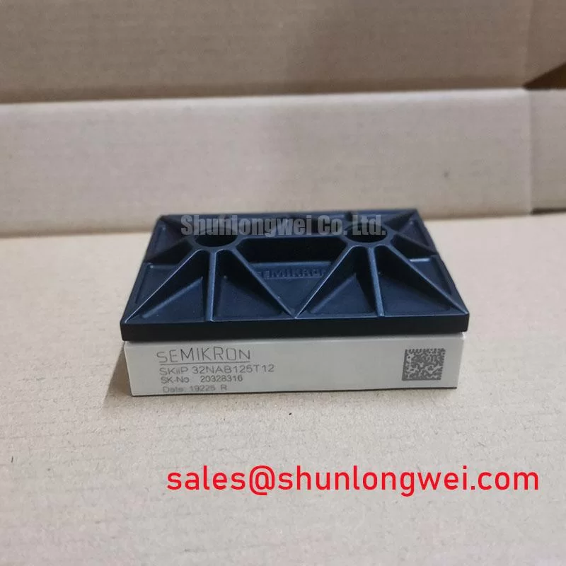
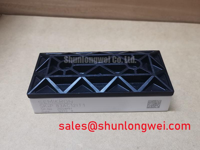
SKIIP83AC12IT1: Technical Deep Dive into the 1200V, 83A CIB IPM Module
Introduction & Key Highlights
Engineered for Uncompromised Reliability in Demanding Drive Applications
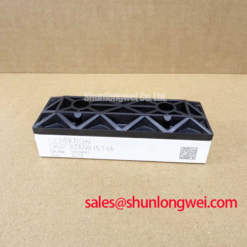
The SKIIP83AC12IT1 from Semikron is an intelligent power module (IPM) that delivers exceptional long-term reliability and thermal performance for compact motor drives through its solder-free pressure contact technology and integrated system design. This module combines a 1200V / 83A 3-phase inverter with a 3-phase brake chopper, providing a robust power stage solution. Key benefits include superior thermal cycling capability and simplified system assembly. This IPM directly addresses the need for resilient, long-life power stages in demanding industrial environments by eliminating failure-prone solder layers. For industrial drives up to 75 kW requiring superior thermal robustness, this integrated pressure-contact module is the optimal design choice.
Application Scenarios & Value
System-Level Benefits of Integrated Design and Solder-Free Reliability
The SKIIP83AC12IT1 is engineered for high-performance power conversion systems where operational uptime and reliability are critical. Its primary application is in industrial Variable Frequency Drives (VFDs) and servo drives that control AC motors in equipment such as conveyors, pumps, fans, and automated machinery. A key engineering challenge in these systems, particularly those with high-inertia loads, is managing the energy generated during deceleration. The module's integrated 3-phase brake chopper provides a built-in solution for regenerative braking, efficiently dissipating this energy and preventing DC link overvoltage conditions, thus enhancing system safety and control.
What is the primary benefit of its pressure-contact design? Enhanced long-term reliability by eliminating solder fatigue. The core value of the SKIIP83AC12IT1 lies in its use of SKiiP® pressure contact technology. Unlike conventional soldered modules, this design eliminates the solder layer between the DCB substrate and the baseplate, which is a common point of failure due to thermal cycling stress. This makes the module exceptionally robust in applications with frequent temperature swings, leading to a significantly longer operational lifespan and lower total cost of ownership. For drive systems requiring different power ratings, the related SKIIP38AC12T4V1 offers a solution for lower-power requirements, while the SKiiP39GA12T4V1 can be considered for alternative configurations.
Key Parameter Overview
Decoding Electrical and Thermal Specs for Drive System Optimization
The specifications of the SKIIP83AC12IT1 are tailored for high-efficiency and reliable operation in industrial power systems. The following table provides a functionally grouped overview of its critical parameters.
| Inverter Stage - Absolute Maximum Ratings (per switch) | |
|---|---|
| Collector-Emitter Voltage (V_CES) | 1200 V |
| DC Collector Current (I_C), T_case = 25°C | 83 A |
| DC Collector Current (I_C), T_case = 70°C | 120 A |
| Gate-Emitter Voltage (V_GES) | ± 20 V |
| Inverter Stage - Characteristics (T_j = 125°C) | |
| Collector-Emitter Saturation Voltage (V_CEsat), I_C = 100A | Typ. 2.1 V |
| Brake Chopper - Absolute Maximum Ratings (per switch) | |
| Collector-Emitter Voltage (V_CES) | 1200 V |
| DC Collector Current (I_C), T_case = 25°C | 75 A |
| Thermal and Mechanical Characteristics | |
| Total Power Dissipation (P_tot), T_case = 25°C | 780 W |
| Operating Junction Temperature (T_jop) | -40 to +150 °C |
| Thermal Resistance, Junction to Case (R_th(j-c)), per IGBT | 0.16 °C/W |
Download the SKIIP83AC12IT1 datasheet for detailed specifications and performance curves.
Technical Deep Dive
An Analysis of Pressure Contact Technology for Enhanced Thermal Cycling
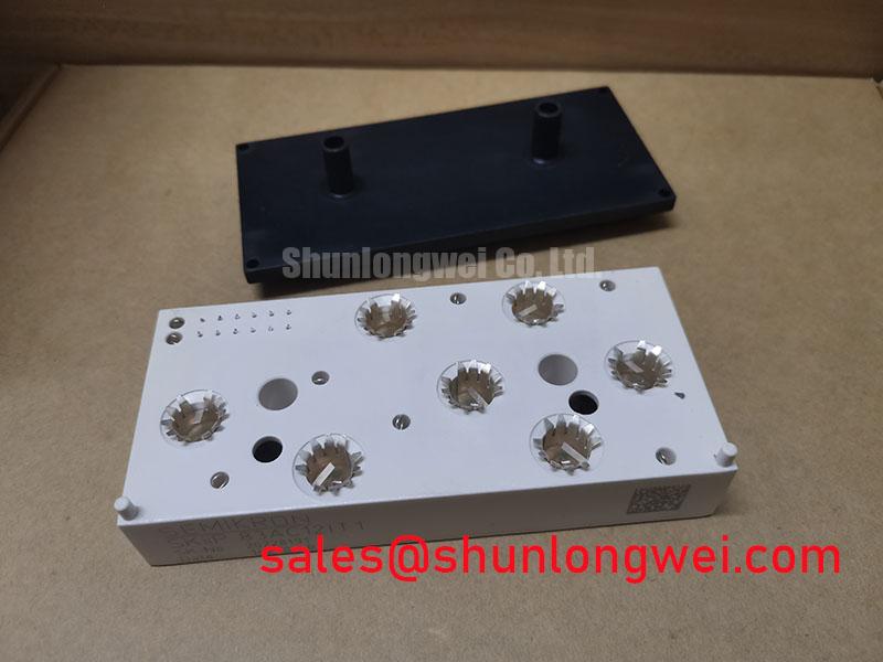
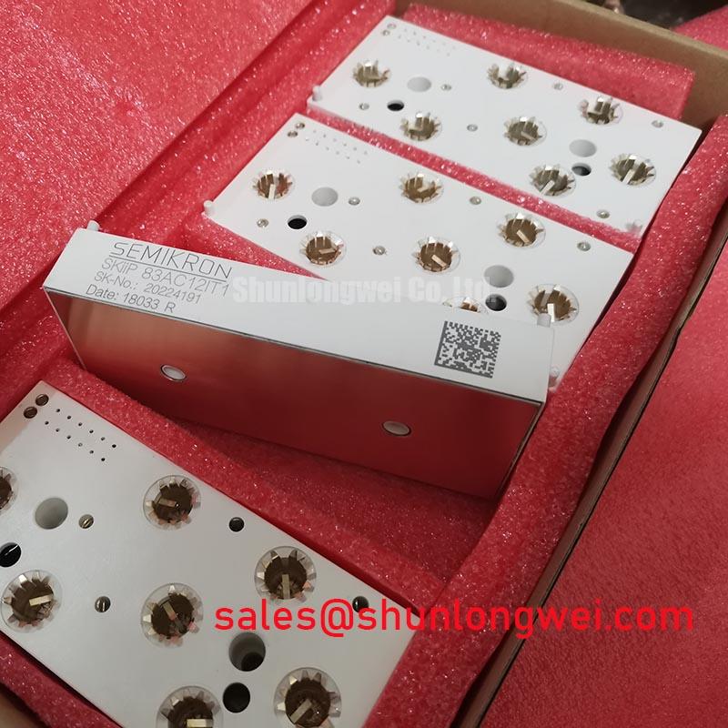
A defining feature of the SKIIP83AC12IT1 is its reliance on pressure contact technology, a design choice that fundamentally enhances module longevity. In a conventional power module, multiple layers, including the silicon chip, a DCB substrate, and a copper baseplate, are joined by solder. Over time, the repeated expansion and contraction caused by temperature fluctuations (thermal cycling) induces mechanical stress in these solder layers, leading to crack propagation and eventual failure. This is a primary wear-out mechanism in high-power electronics.
The SKiiP design cleverly circumvents this issue. By applying a precise mounting pressure, it establishes a direct, solder-free thermal and electrical connection between the DCB and the system's heatsink. What is the engineering analogy for this technology? It's like replacing a glued structural joint with a high-tension bolted connection. While the glue (solder) is susceptible to fatigue from repeated stress, the bolted connection (pressure contact) maintains its integrity, ensuring a consistent, low-resistance thermal path throughout the module's life. This results in superior power cycling capability and a more predictable operational lifetime, a critical advantage in applications like wind turbine inverters and industrial motor drives where maintenance is costly and reliability is paramount. This concept is a cornerstone of designing for long-term field reliability, a topic further explored in our guide on mastering IGBT thermal management.
Frequently Asked Questions
Engineering Inquiries on Integration, Performance, and Reliability
How does the pressure contact system affect the mounting process compared to standard modules?
The mounting process for the SKIIP83AC12IT1 requires a specific, uniform pressure to be applied across the module to ensure proper electrical and thermal contact. This is typically achieved using a calibrated mounting clamp system rather than simple screw holes. While it requires a different assembly procedure, it eliminates the need for thermal grease application and potential inconsistencies associated with manual torquing, leading to a more repeatable and reliable thermal interface.
What is the practical impact of the typical V_CEsat of 2.1V at 100A and 125°C?
The V_CEsat value is a direct indicator of the module's conduction losses—the heat generated while the IGBT is in the 'on' state. A V_CEsat of 2.1V at a high operating current and temperature signifies efficient performance from the Trench IGBT technology used. Lower conduction losses mean less waste heat is generated for a given amount of current, which allows for the use of a smaller, more cost-effective heatsink, improves the overall energy efficiency of the VFD, and helps maintain a lower junction temperature, further contributing to the module's long-term reliability. For a deeper understanding of this crucial parameter, explore our guide on decoding IGBT datasheets.
Design & Integration Support
Evaluating the SKIIP83AC12IT1 for Your Power System
For engineering teams developing next-generation industrial drives, servo systems, or renewable energy inverters, the SKIIP83AC12IT1 offers a compelling combination of high integration and proven reliability. Its robust, solder-free design provides a tangible advantage in applications where thermal stress is a major concern. We encourage you to review the official datasheet to analyze its performance curves and evaluate how its integrated features can streamline your design process and enhance the field reliability of your end product.