

Content last revised on October 11, 2026
Assembly Integrity & Layout Architecture: Evaluating High-Altitude Reliability for SKM400GA173D
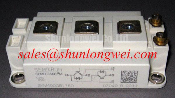
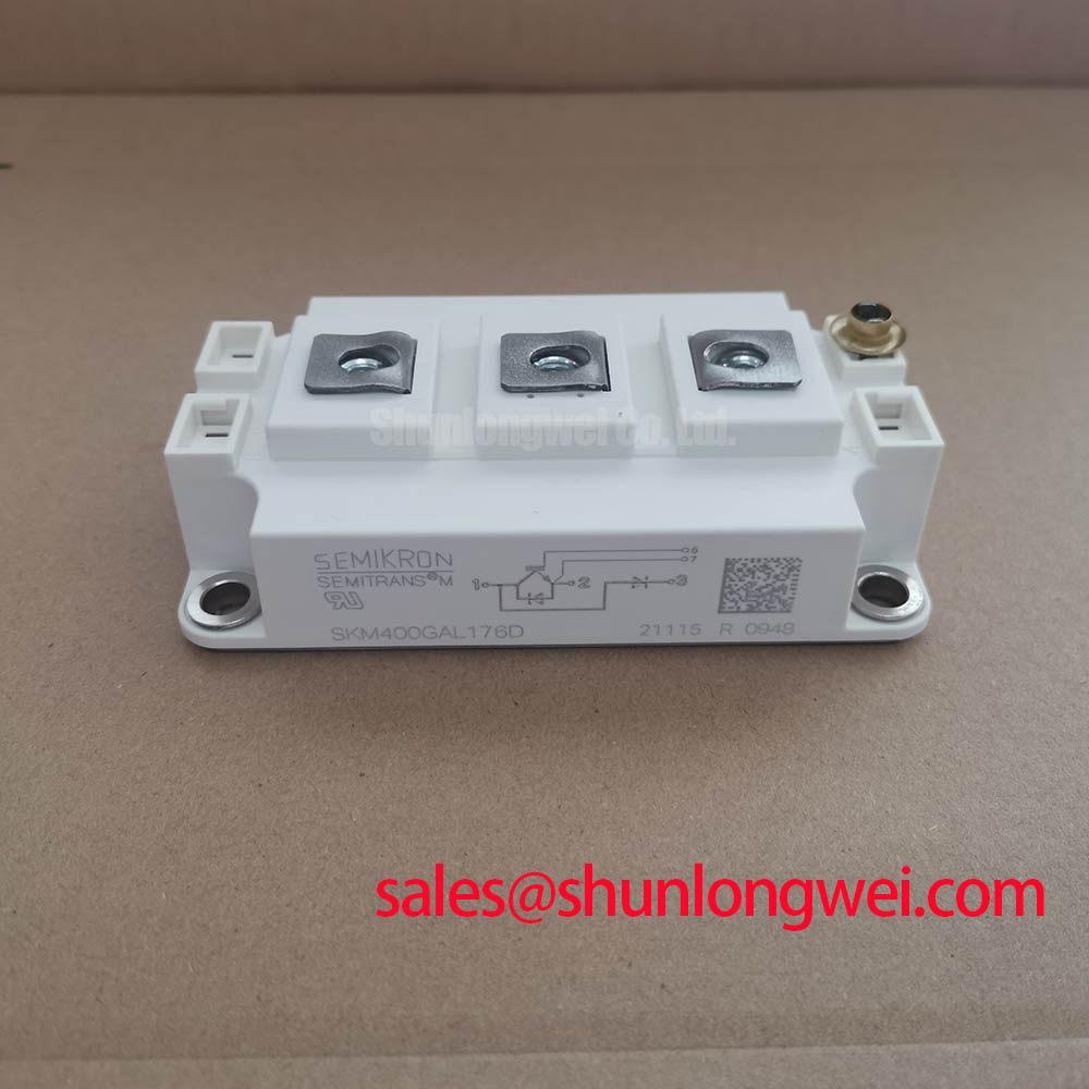
I check the recorded DC-link voltage and installation environment before assessing whether an SKM400GA173D replacement has adequate electrical headroom. The supplied official specifications identify a 1700 V voltage rating and a 400 A current rating. These are component boundaries, not a declaration that a particular converter operating point, installation altitude, or switching transient is acceptable.
Design Consideration: For elevated-altitude installations, assess terrestrial-neutron exposure separately from ordinary switching overstress. Semiconductor susceptibility to single-event burnout depends on device-specific behavior and operating conditions; neither the package name nor the voltage rating supplies a failure-rate curve. An engineering assessment should use manufacturer-supported susceptibility data and an applicable environmental radiation model before assigning a FIT value or an altitude-dependent voltage limit. Treat reduced blocking-voltage stress as a consideration for evaluation, not as a quantified reliability guarantee.
The practical distinction matters during fault investigation. A recorded collector-emitter overshoot points toward a switching-stress investigation, whereas an unexplained damaged device does not establish a cosmic-ray event. Preserve the operating logs, protection records, bus-voltage history, and physical position of the affected module. Compare these with cooling conditions and neighboring power-stage behavior before classifying the failure mechanism. Visual damage alone cannot establish a FIT rate or identify single-event burnout.
For compatibility assessment, a utility-scale 1500 V central solar photovoltaic inverter is a possible evaluation context, not an approved application implied by the part number. Designers should examine the actual converter topology, maximum DC-link operating conditions, switching overshoot, and fault behavior. The relationship between the equipment’s nominal voltage class and the module’s blocking rating requires evaluation at the switching device terminals.
Assembly layout also affects that assessment. As a Design Consideration, inspect the busbar-to-terminal fit, fastening accessibility, and separation between energized conductors and grounded hardware. Clearance and creepage requirements belong to the equipment’s insulation coordination, including pollution conditions and installation environment. Maintain the intended conductor geometry when replacing the module; an altered busbar stack or displaced insulating support can change both electrical spacing and commutation behavior.
Benchtop Waveform Tuning: Mitigating Stress via Separating Driver Return from Main Current on SKM400GA173D
Trace the gate-driver return through the actual terminal drawing before connecting a measurement probe or modifying the driver harness. A connection that shares load-current impedance can shift the driver’s local reference during switching. However, an auxiliary Kelvin emitter must not be inferred from the Semitrans designation: use the documented terminal functions to establish whether a separate driver-return connection exists and how it should be connected.
Design Consideration: Where a documented auxiliary emitter connection is provided, keep the gate-drive current path distinct from the main power-current path. Where it is not provided, evaluate the shared return impedance explicitly. Measure gate-emitter voltage at the module’s relevant terminals with an appropriate differential probing arrangement, while observing collector-emitter voltage and load current. This helps distinguish actual gate excursions from probe-reference artifacts and identifies whether switching transitions disturb the driver reference.
Miller-related gate movement should be evaluated during the opposing device’s switching transition rather than judged from an unloaded driver waveform. The relevant observations include the off-state gate excursion, driver sink behavior, and evidence of unintended conduction. Gate damping, turn-off impedance, and any clamping strategy remain system-selected measures whose effectiveness should be checked across the intended operating conditions.
Design recommendation: Keep parallel power paths and their gate-return arrangements geometrically balanced, then use double-pulse measurements to assess switching overshoot and current sharing.
For parallel modules, distinguish static conduction sharing from dynamic switching sharing. A positive temperature coefficient of collector-emitter saturation voltage can assist static sharing only within the operating region where that behavior is established by the device characteristics. Do not assign that characteristic to SKM400GA173D without the relevant curves. Compare conduction voltage at matched current and temperature, and examine branch current during turn-on and turn-off; equal busbar lengths alone do not establish equal switching behavior.
Protection validation belongs in the same waveform review. As a Design Consideration, evaluate desaturation detection, blanking behavior, and controlled turn-off against the device’s documented short-circuit operating limits. Excessively abrupt fault interruption can create additional voltage stress, while delayed detection can increase deposited energy. Neither the 400 A rating nor a successful normal-load test establishes short-circuit withstand capability.
In a broader power-conversion assembly, an associated device such as SKET400/12E should be evaluated by its own circuit role and ratings. Front-end behavior influences DC-link conditions, but it does not establish compatibility with the IGBT module or determine the gate-driver design.
Benchtop Screening: Pre-Installation Junction Health Check for SKM400GA173D
Disconnect the SKM400GA173D from the power circuit and driver before taking cold terminal measurements, and verify that stored energy has been discharged. Connected snubbers, driver resistors, and other semiconductor branches can obscure the result. Use the module circuit diagram to identify the collector, emitter, gate, and any documented diode path before applying the meter leads.
Design Consideration: With the gate held at emitter potential by an appropriate handling arrangement, use diode-check mode to compare main-terminal behavior in both polarities. If the documented circuit includes an antiparallel diode, evaluate the corresponding forward path and reverse blocking indication. Record meter type, lead polarity, and module temperature. A handheld meter’s stimulus and display do not reproduce the manufacturer’s forward-voltage test conditions, so avoid treating a particular displayed threshold as a universal acceptance limit.
An unexpected low-impedance path warrants further investigation, but its cause should not be assigned from a single reading. Repeat the measurement after confirming isolation from external circuitry and compare with a known-good module under equivalent conditions. Gate charging can also affect apparent collector-emitter conduction during handling; consistent gate control is essential when comparing results.
Gate-emitter checks can identify gross abnormalities, but a multimeter resistance reading is not a calibrated gate-leakage qualification. Formal leakage assessment requires controlled bias, suitable instrumentation, and the specified acceptance conditions. Keep screening voltages within the documented gate limits. For a wider diagnostic workflow, the Field Engineer’s Handbook provides a useful companion to the module-specific service procedure.
Cross-model sourcing should follow the same evidence-based approach. The SKM200GAL126D is a comparison candidate only after checking topology, blocking capability, current-rating conditions, terminal arrangement, mounting geometry, and driver requirements. A related model designation does not establish a drop-in replacement, and cold screening cannot compensate for an electrical or mechanical mismatch.
SKM400GA173D Operational Boundaries: Evaluating Terminal-to-Baseplate Insulation Test Limits
Establish the approved terminal-to-baseplate test configuration before attaching an insulation tester. Disconnect external electronics and determine which terminals must be grouped, which must remain isolated, and how the assembly must be discharged afterward. A routine insulation-resistance measurement and a dielectric withstand test are different procedures; their test voltages and acceptance criteria are not interchangeable.
Design Consideration: Use the manufacturer-authorized procedure rather than imposing a generic megohmmeter voltage or resistance threshold on this module. Record test duration, temperature, humidity, instrument settings, and terminal grouping so that repeat measurements are comparable. A resistance result can reflect surface contamination or fixture leakage as well as an internal problem; it does not, by itself, verify a particular substrate material or prove internal ceramic integrity.
Inspect exposed insulation surfaces and the surrounding mounting area for conductive deposits, moisture traces, and damaged barriers. Clean using an assembly-compatible process, then repeat the permitted measurement under controlled conditions. Creepage assessment concerns the complete installed path, including nearby busbars and grounded hardware, rather than the module housing alone.
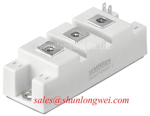
The manufacturer’s Semikron MiniSKiiP® Power Modules information illustrates why mounting and interface instructions belong to a specific product family. MiniSKiiP is a different family; its construction, assembly practices, and insulation details should not be transferred to the Semitrans SKM400GA173D.
After permitted insulation checks, assess the thermal interface before returning the assembly to service. As a Design Consideration, control mating-surface cleanliness, flatness, thermal-interface coverage, and the specified fastening sequence. Excess interface material or uneven clamping can impair heat transfer. Use the module’s mounting instructions for compound application and tightening torque rather than borrowing values from another package.
For pulsed operation, evaluate junction-temperature excursions using the applicable transient thermal-impedance characteristics and the measured loss profile, rather than relying solely on steady-state thermal resistance. Repeated heating and cooling should inform the equipment’s thermal-control strategy, without assigning an unsupported service-life figure. During recommissioning, record baseplate temperature, cooling performance, and switching behavior under a controlled load progression so that the repaired assembly has a traceable operating baseline.