Content last revised on October 31, 2026
SKM800GA126D Operational Boundaries: Heatsink Contact Pressure and Operating Limits
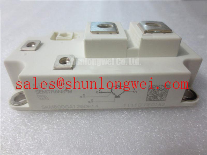
Inspect the heatsink contact surface and retained thermal compound before removing a SKM800GA126D from a failed power stage; uneven compound transfer can help distinguish an assembly problem from a cooling airflow problem. Record the module position, terminal connections, and temperature history before cleaning away that evidence. The Semikron IGBT module should be assessed together with its mounting interface and driver circuit, rather than treated as an isolated replacement item.
Check the heatsink for raised burrs, embedded particles, and uneven contact marks before applying fresh thermal interface material. As a Design Consideration, the compound should fill surface irregularities without becoming an unnecessarily thick thermal barrier. Assess coverage using the approved application method and assembly inspection procedure; a universal grease thickness is not a substitute for the module mounting instructions and the selected compound’s processing requirements.
The supplied official electrical specifications identify a collector-emitter voltage of 1200 V and a continuous collector current of 800 A at a case temperature of 25°C. These are distinct operating boundaries: the current rating depends on its stated thermal condition, while switching operation also introduces transient voltage and power dissipation. During equipment assessment, relate the actual case temperature and load profile to the applicable operating curves rather than carrying the cold-case current rating directly into a hot enclosure.
Two further official specification entries are VCE(sat) of 1.70 V at 600 A and a junction temperature of 25°C, and typical total switching losses of 110 mJ. The saturation-voltage figure describes a particular conduction test point. The switching-energy figure needs its associated voltage, current, gate-drive, and temperature conditions before it can support a cooling calculation; it is not a fixed loss for every switching event.
For thermal assessment, use the applicable transient thermal impedance network to relate changing dissipation to junction-temperature excursions. This is an Engineering Recommendation, particularly where intermittent loading produces thermal peaks that a steady-state heatsink reading does not capture. Compare temperature measurements under repeatable load and airflow conditions, keeping the sensor position consistent so that maintenance records remain useful.
Mounting pressure should come from the specified fastener sequence and calibrated tightening procedure, not from attempting to flatten a visibly distorted assembly. Inspect baseplate and heatsink profiles against their permitted tolerances. Do not assume that additional compound or increased screw torque can compensate for unacceptable curvature. Maintain access and clearance around the mounting points so tools can engage squarely without loading nearby control terminals.
Preventing Spurious Faults: Gate Resistance Checks When Replacing SKM800GA126D
Separate turn-on and turn-off gate-resistance checks when investigating trips after a module replacement. As a Design Consideration, changing either resistance affects switching behavior differently: turn-on adjustment influences current rise and commutation, while turn-off adjustment influences voltage overshoot and the discharge of gate charge. Compare the installed resistor network with the approved driver schematic before attributing changed behavior to the power module.
Capture gate-emitter and collector-emitter waveforms with appropriately rated measurement equipment and a controlled test procedure. Examine switching transitions, ringing, and driver-supply behavior together. Increasing resistance can reduce transition speed but also increase switching dissipation; reducing it can expose parasitic inductance and driver limitations. The final values should follow measured behavior across the intended operating conditions, not a resistor value borrowed from another module family.
In replacement planning, SKM200GAL126D is a related part number for comparison, not an established drop-in substitute for SKM800GA126D. The comparison below separates the supplied SKM800GA126D specifications from characteristics that require an independent datasheet review.
| Replacement assessment item | SKM800GA126D | SKM200GAL126D |
|---|---|---|
| Manufacturer | Semikron | Semikron |
| Collector-emitter voltage | 1200 V, official specification | Consult datasheet |
| Continuous collector current | 800 A at case temperature 25°C, official specification | Consult datasheet |
| Conduction test point | 1.70 V at 600 A and junction temperature 25°C, official specification | Consult datasheet |
| Mechanical and driver interchangeability | Reference assembly to be matched | Requires independent verification; not established here |
Review desaturation protection against the actual switching waveform. As an Engineering Recommendation, blanking must accommodate the normal turn-on transition without concealing a developing fault for longer than the device and driver protection limits permit. Detection delay, filtering, propagation delay, and shutdown behavior all belong in that assessment. The normal on-state voltage test point alone does not define a valid short-circuit detection threshold.
Where the driver supports staged soft turn-off, assess whether its discharge sequence limits fault-related overshoot while still interrupting current within the permitted protection window. Neither a fixed detection delay nor a universal staged shutdown profile should be assigned to this module without the relevant protection specifications. For a potential high-speed rail or heavy freight locomotive traction inverter replacement, engineers should also establish equipment-level electrical, mechanical, and qualification compatibility before accepting the part.
Assembly Integrity & Layout Architecture: Suppressing Capacitively Induced Gate Voltage Spikes in SKM800GA126D
Keep the gate-drive outgoing and return paths close together, and inspect the return connection for shared power-current impedance. As a Design Consideration, collector voltage transitions can couple displacement current through reverse-transfer capacitance into the gate circuit. An unintended gate-voltage rise therefore requires examination of both driver impedance and the physical connection path, rather than assuming the resistor alone controls it.
An active Miller clamp can provide a low-impedance discharge path when supported by the driver architecture. Its connection should avoid a long loop that defeats the intended clamping action. Negative off-state bias is another system-level option, but its magnitude must remain within the module’s gate limits and the driver’s operating capability. Check the measured gate excursion at the module terminals, including negative undershoot, before accepting either approach.
Where the verified terminal drawing provides a separate control-emitter connection, route the driver return accordingly rather than sharing the high-current emitter path. This is an Engineering Recommendation, not a claim that an undocumented auxiliary terminal exists on every package variant. Preserve insulation spacing around the gate circuit and power connections according to the equipment’s applicable insulation-coordination requirements.
The supplied official specification includes an isolation voltage of 2500 V AC. That test rating should not be interpreted as an allowable continuous working voltage or as proof of complete equipment insulation compliance. Keep terminal contamination, moisture, and condensation under control, and use the specified inspection and test procedure after any event that could compromise insulation surfaces.
When reviewing associated power stages, the SKET400/08E is a separate device to assess against the actual front-end or auxiliary-stage schematic. If that circuit uses phase-controlled rectification, firing behavior and input harmonics require their own evaluation; changing the IGBT gate network does not correct rectifier-side distortion. Any MOV absorption network likewise needs coordination with the actual transient energy and protection arrangement.
For conductor heating context, skin effect and proximity effect explain why alternating current distribution can increase conductor losses. These mechanisms support examining bus and connection geometry, but they do not establish a switching limit for SKM800GA126D. Broader layout and driver considerations are covered in the IGBT Design & Integration technical guide.
Assembly Integrity: Managing Thermal Grease Pump-Out for SKM800GA126D
Inspect the thermal interface for edge migration, dry regions, and changes in the contact imprint when the module is removed during scheduled service. As a Design Consideration, repeated thermal expansion can redistribute some interface materials, but an uneven imprint alone does not establish pump-out as the cause of overheating. Compare it with heatsink flatness, mounting records, airflow condition, and the previous temperature trend.
Clean mating surfaces using a process compatible with the assembly materials, then inspect for damage before reapplication. Use the approved compound quantity and distribution method, followed by the manufacturer’s specified tightening sequence. A diagonal, progressive sequence may be appropriate where the mounting instructions require it; the actual torque and interface thickness must follow those instructions rather than a generic workshop value.
Set inspection intervals from operating duty, environmental contamination, and observed temperature trends instead of assigning an unsupported service-life interval to the grease. Include fan operation, filter loading, fin blockage, and terminal-joint condition in the maintenance record. After cold storage or a large ambient-temperature change, assess condensation before energizing exposed power and control connections.
Maintenance Note: Trend terminal and heatsink temperatures under comparable load conditions, and check the airflow path before retightening connections or disturbing the thermal interface.
After reassembly, record compound identification, tightening-tool calibration status, mounting sequence, and the resulting thermal measurements. If temperatures remain uneven, investigate contact quality and cooling distribution separately so that another disassembly addresses an observed defect rather than simply repeating the same installation procedure.