Content last revised on February 28, 2026
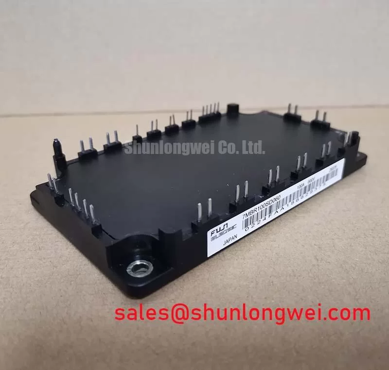
7MBR30NE060 Fuji Electric 600V 30A PIM IGBT Module
The 7MBR30NE060 is a high-integration PIM (Power Integrated Module) from Fuji Electric, delivering a 600V/30A 7-pack configuration designed to minimize PCB footprint in low-power industrial drive systems. This module consolidates the three-phase rectifier, brake chopper, and three-phase inverter into a single P612 package, streamlining assembly for AC servo drives and uninterruptible power supplies (UPS).
Top Specs: 600V | 30A | P612 (7-pack) Package
- System Integration: Combines converter, brake, and inverter stages to reduce parasitic inductance and design complexity.
- Enhanced Reliability: Features an integrated NTC thermistor for precise real-time temperature monitoring and protection.
For designers questioning how to handle startup surges in high-torque motors, the 7MBR30NE060 manages transient loads effectively through its robust SCSOA (Short Circuit Safe Operating Area). For servo drives prioritizing thermal margins and board density, this 600V module represents the optimal technical choice.
Key Parameter Overview
Decoding the Specs for Enhanced Thermal Reliability
To support engineering evaluation, the following table highlights the critical performance metrics of the 7MBR30NE060. Understanding these parameters is essential for calculating system efficiency and heat sink requirements.
| Parameter | Official Value | Engineering Significance |
|---|---|---|
| Collector-Emitter Voltage (Vces) | 600V | Standard rating for 200V-240V AC line input systems. |
| Collector Current (Ic) | 30A (at Tc=80°C) | Continuous current handling for low-to-medium power motors. |
| Saturation Voltage Vce(sat) | Typ. 2.10V | Directly influences conduction losses during heavy load cycles. |
| Configuration | 7-pack (PIM) | Full integration of converter, brake, and inverter stages. |
| Isolation Voltage | 2500V AC (1 min) | Ensures safety and compliance with international dielectric standards. |
Download the 7MBR30NE060 datasheet for detailed specifications and performance curves from Fuji Electric.
Application Scenarios & Value
Achieving System-Level Efficiency in Low-Power Inverter Designs
The 7MBR30NE060 excels in environments where board space is at a premium. Think of the PIM package as an all-in-one workstation; by grouping the converter, brake, and inverter in one "desk," it eliminates the travel time (inductance) and space wasted between separate discrete components. This is particularly valuable in Variable Frequency Drives (VFD) and Servo Drive amplifiers where compact enclosures often restrict airflow.
In a typical PWM control motor application, designers face the challenge of managing parasitic inductance which leads to voltage spikes during switching. The internal layout of the 7MBR30NE060 is optimized to keep these loops short. By utilizing the integrated brake stage, engineers can implement precise deceleration profiles without needing external chopper modules. While this model is ideal for 30A continuous operation, for systems requiring higher current handling, the 7MBR50NF-060 offers a higher rating of 50A within a similar architecture.
This module's NPT (Non-Punch Through) technology provides a positive temperature coefficient for the saturation voltage, making it inherently suitable for IGBT Paralleling if higher current capacities are required in future design iterations. Its application extends to medical equipment and robotic servo drives, where reliability under varied load conditions is non-negotiable.
Technical & Design Deep Dive
Understanding the Efficiency Gains of the 7-Pack Integration
The internal architecture of the 7MBR30NE060 is centered on Fuji’s N-Series chip technology. This design focuses on balancing low switching losses with rugged short-circuit capability. One of the most critical design factors is the Thermal Resistance (Rth(j-c)). The Rth(j-c) value acts like the diameter of a high-pressure hose—the lower the resistance, the faster heat (the energy) can flow away from the silicon core to the heatsink "drain." For the 7MBR30NE060, the optimized thermal path allows for higher power density without exceeding the maximum 150°C junction temperature.
Furthermore, the PIM (Power Integrated Module) approach inherently improves EMC (Electromagnetic Compatibility). By reducing the number of external interconnects between the rectifier and the inverter stage, the loop area that acts as an antenna for EMI is significantly reduced. This simplifies the filtering requirements needed to meet IEC 61800-3 standards for industrial drives. For a deeper understanding of these technologies, engineers can explore our guide on IGBT module integration.
Frequently Asked Questions
Engineering Insights for Design Optimization
What is the primary benefit of the 7-pack PIM configuration for 7MBR30NE060?
The primary benefit is the reduction in total system size and parasitic inductance. By integrating the converter, brake, and inverter, it eliminates the need for complex external busbars and simplifies the Gate Drive layout.
How does the integrated NTC thermistor assist in system protection?
The thermistor allows the controller to monitor the module's substrate temperature in real-time. This enables active thermal management, such as derating the PWM frequency or triggering a shutdown before the IGBTs reach critical junction temperatures.
Can the 7MBR30NE060 handle 240V AC input systems?
Yes. With a Vces of 600V, the module provides a sufficient safety margin for DC bus voltages resulting from rectified 240V AC (typically around 340V DC), accommodating standard industrial voltage fluctuations.
What considerations are needed for the brake chopper stage?
The brake IGBT is rated at the same 30A current as the main inverter stages. Designers must ensure that the external braking resistor is sized correctly to prevent exceeding the pulsed collector current limits during rapid motor deceleration.
Strategic integration of power components is no longer an option but a necessity in the push toward Industrial 4.0. As systems demand higher efficiency in smaller form factors, modules like the 7MBR30NE060 provide the foundational reliability required for the next generation of automated drives. Engineers looking to further optimize their power stages should consult our comprehensive knowledge base on module selection to ensure long-term system stability.