Content last revised on August 28, 2026
Engineering Evaluation of the CM1000E3UA-24D IGBT Module: Power Density and Thermal Reliability
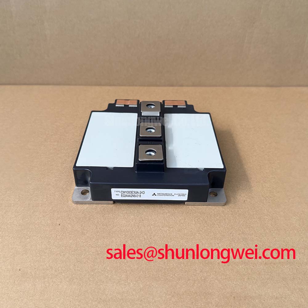
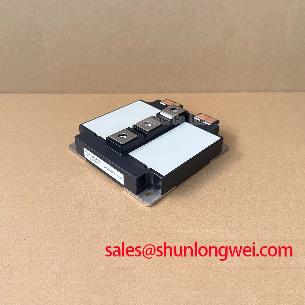
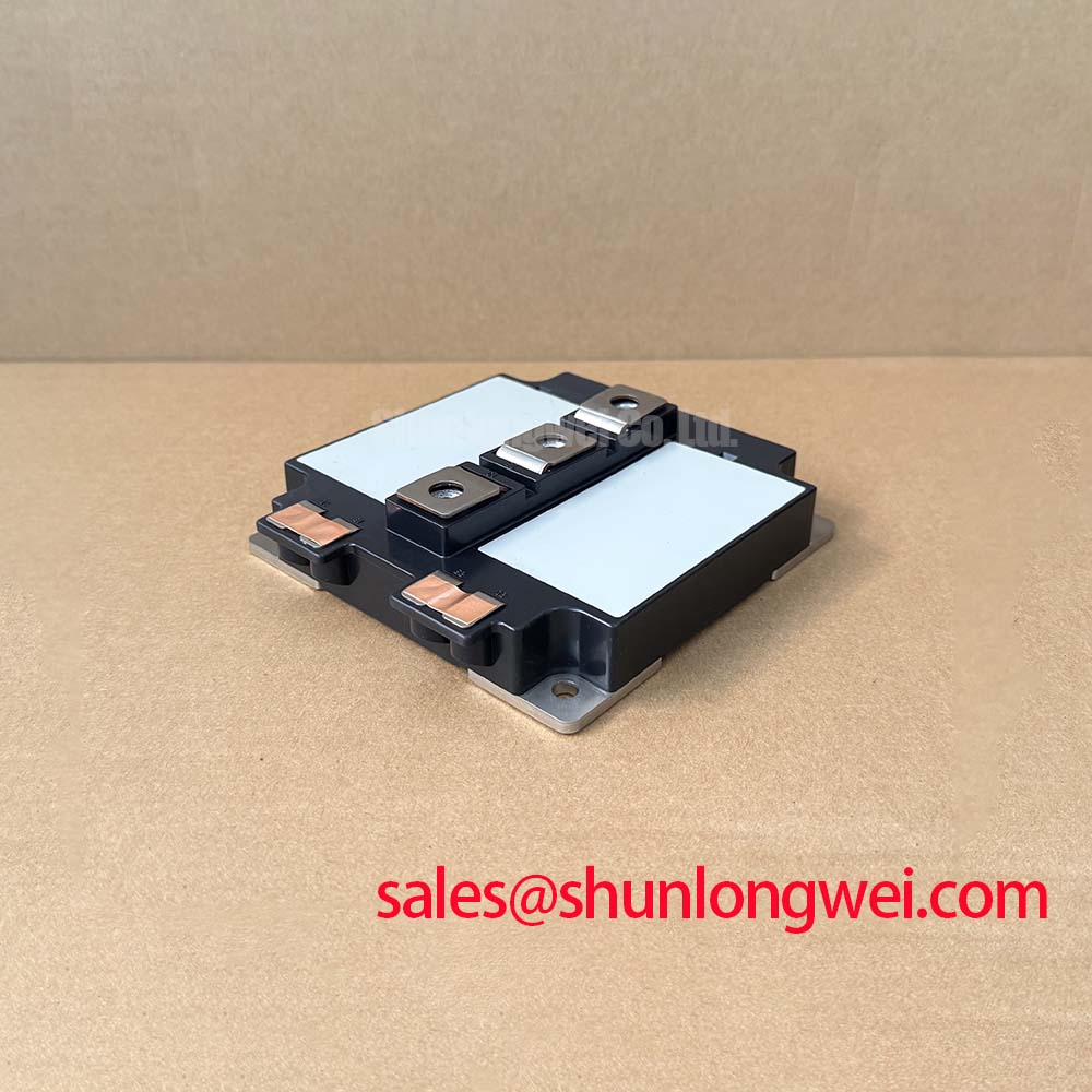
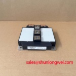
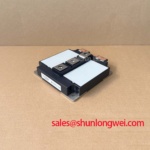
The CM1000E3UA-24D, manufactured by Mitsubishi, is a high-power industrial semiconductor module. The module delivers robust performance in high-power applications by minimizing thermal resistance and thermal stress during harsh switching cycles.
Key Specs: 1200V | 1000A | MODULE Package.
Key Benefits: Low conduction losses; exceptional thermal cycling life.
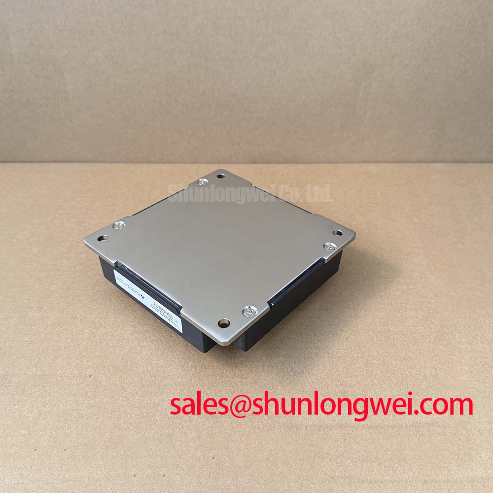
What is the primary benefit of its isolated baseplate design? Enhanced thermal reliability by reducing junction-to-case thermal resistance.
For heavy-duty motor drives requiring maximum thermal headroom, this 1200V 1000A module is the optimal choice.
Application Scenarios & Value
Achieving System-Level Benefits in High-Frequency Power Conversion
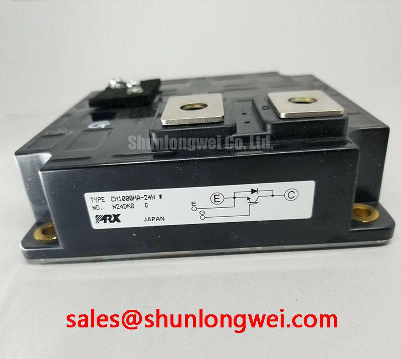
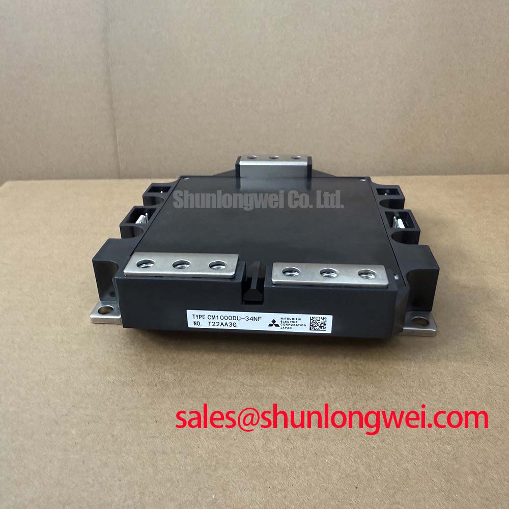
Engineers often face severe thermal transients during start-up operations in heavy industrial motor control systems. For instance, in mining conveyor systems, high load inertia demands immense surge currents that can quickly raise the junction temperature of a switching device, leading to catastrophic failure. The CM1000E3UA-24D addresses this challenge with its continuous collector current of 1000A and high pulse current capability. This allows system designs to withstand rapid power cycling without experiencing immediate package degradation. Additionally, this module incorporates a robust free-wheeling diode that clamps inductive spikes during fast switching turn-off events. Designers utilizing this module can achieve superior thermal stability in high-capacity grid inverters and heavy transportation systems. While the single-switch or chopper configuration of the CM1000E3UA-24D is optimized for specific inverter topologies, applications requiring a dual half-bridge configuration can utilize the related CM1000DU-34NF, or the CM1000HA-24H for standard single-switch setups.
Technical & Design Deep Dive
Advanced Thermal Interface and Loss Minimization in High-Current Switching
Achieving high reliability in high-current environments requires a detailed look at the module's thermal paths and switching characteristics. A comprehensive analysis of IGBT modules indicates that physical packaging determines operational lifetime. The CM1000E3UA-24D features an isolated baseplate with a high isolation voltage rating of 2500V AC (RMS, 1 minute). This construction drastically reduces the thermal resistance from junction to case (Rth(j-c)). In engineering terms, thermal resistance behaves like a wide highway for thermal energy; a lower resistance allows heat to quickly bypass bottleneck areas and reach the heatsink, preventing a destructive thermal pileup at the junction.
Furthermore, conduction efficiency is governed by the collector-emitter saturation voltage (VCE(sat)), which typically registers at 2.1V under rated current. The saturation voltage functions like the friction in a water pipe. A lower saturation voltage means less resistance to current flow, ensuring that minimal energy is wasted as heat during conduction. In high-power systems like a variable frequency drive (VFD) or industrial power supply, this parameter directly limits the maximum heatsink temperature, allowing designers to reduce the size and cost of the cooling system. This enables compact, high-density system designs that operate well within the device's Safe Operating Area.
Key Parameter Overview
Decoding the Specs for Enhanced Thermal Reliability
The following table highlights the essential operational thresholds for the module. Understanding these limits is critical when selecting parameters using a practical guide to voltage, current, and thermal management.
| Parameter | Symbol | Rating / Value | Unit |
|---|---|---|---|
| Collector-Emitter Voltage | VCES | 1200 | V |
| Continuous Collector Current | IC | 1000 | A |
| Peak Collector Current (Pulse) | ICRM | 2000 | A |
| Collector-Emitter Saturation Voltage (Typ) | VCE(sat) | 2.1 | V |
| Isolation Voltage (AC, 1 min) | Visol | 2500 | V |
| Operating Junction Temperature Range | Tvj | -40 to +150 | °C |
FAQ
Addressing Common Engineering Queries on Thermal and Electrical Integration
To assist design engineers during the evaluation phase, several frequent integration questions are answered below. For deeper packaging insights, refer to our article on IGBT thermal management.
What is the continuous current rating of the CM1000E3UA-24D, and how does it affect design?
The module features a continuous collector current rating of 1000A. Designers must size the busbars and main terminal connections to carry this load while managing thermal dissipation through a highly optimized heatsink interface.
How does the 1200V collector-emitter voltage rating benefit high-power industrial systems?
The 1200V rating provides a safe margin for systems operating on standard 400V or 480V AC utility grids, protecting the module against transient overvoltages and inductive kickbacks common in heavy-duty inductive switching environments.
Why is the isolated baseplate package critical for thermal management in this module?
The isolated baseplate provides an internal electrical barrier rated at 2500V AC, meaning multiple modules can be mounted to a single heatsink without causing electrical short circuits. This simplifies overall mechanical packaging while ensuring efficient heat transfer.
How does the low typical VCE(sat) of 2.1V impact overall system efficiency?
A lower VCE(sat) reduces steady-state conduction losses. In continuous-duty applications like VFDs or solar inverters, this translates directly to reduced thermal output and lower energy waste, boosting the converter's overall system-level efficiency.
Selecting high-capacity switching modules like this one represents a strategic step toward optimizing power conversion platforms, ensuring long-term hardware reliability in transitioning to higher-efficiency industrial grids.