
Content last revised on August 28, 2026
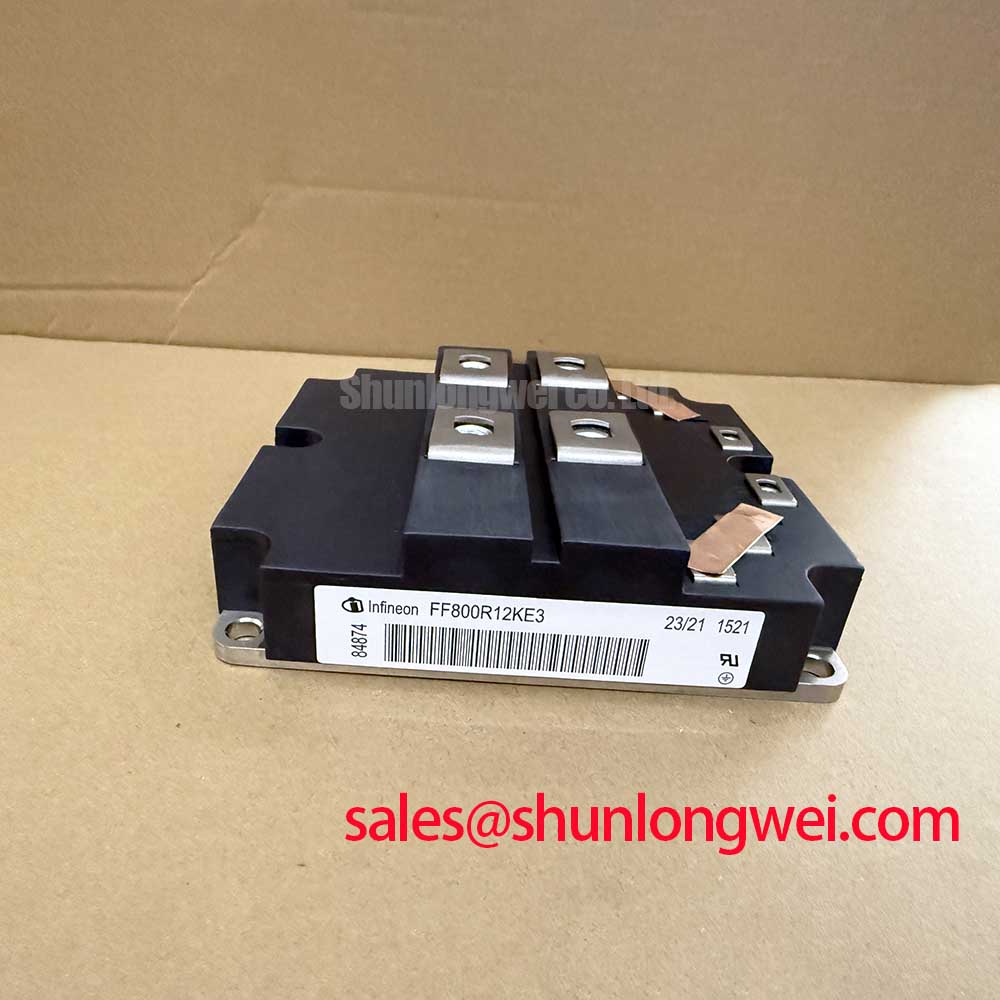
Maximizing Power Density: The Role of the Infineon FF800R12KF4 Dual IGBT Module
Designed for high-current industrial environments, this dual IGBT module delivers exceptional reliability in multi-megawatt conversion systems by optimizing thermal transfer paths under extreme switching loads. Featuring 1200V and 800A ratings, it provides extremely low thermal resistance and excellent short-circuit ruggedness. By utilizing an isolated copper base plate, the module prevents localized thermal stress. This design effectively mitigates the risk of catastrophic failure during transient overloads.
Quick Summary:
- What is the primary benefit of its low thermal resistance? It prevents thermal runaway under high-load switching.
- Where is this module best applied? In high-power industrial drives and renewable energy inverters.
Application Scenarios & Value
Achieving Thermal Reliability in High-Demand Energy Systems
Engineers often face thermal budget limitations in high-power setups. For 1200V systems prioritizing thermal margin, this 800A module is the optimal choice. Typical applications include high-power UPS systems and multi-megawatt industrial motor drives. The low switching losses help systems achieve compliance with electromagnetic compatibility standards such as IEC 61800-3.
In grid-tied renewable energy conversion, maintaining efficiency at high current levels is critical. For setups requiring a larger single-switch current path instead of a dual half-bridge, the related FZ1200R12KF5 offers a single-switch configuration rated at 1200A. Alternatively, for designs with higher voltage demands, engineers might evaluate the FF800R17KE3 with a 1700V breakdown voltage, or the FF900R12IP4 for higher current density.
Technical & Design Deep Dive
Detailed Analysis of the IHM Package and Low Rth(j-c) Technology
The collector-emitter saturation voltage (VCE(sat)) is rated at a maximum of 3.2V (typical 2.7V) at its full rated current of 800A. Lower saturation voltage directly reduces conduction losses. To fully utilize this efficiency, the design of the gate drive circuit must incorporate a negative turn-off gate voltage and active Miller clamping. This prevents parasitic turn-on due to high dV/dt rates during rapid switching transitions.
Think of the junction-to-case thermal resistance (Rth(j-c) of 0.0125 K/W) as a multi-lane highway for heat. Just as a wider highway prevents traffic jams, this low resistance ensures that thermal energy flows freely from the silicon junction to the heatsink. This keeps the peak operating temperature well below its limit. Additionally, the isolated copper base plate acts like a thermal buffer reservoir. During sudden short-circuit events, it acts as a heat sink sponge, temporarily absorbing the massive peak energy spike before it can damage the gate oxide layer.
For a comprehensive overview of selection criteria, consult our power semiconductor selection guide. Understanding these failure modes is critical for system longevity; see the field testing and reliability analysis guide for troubleshooting procedures. To learn more about packaging innovations, review our ultimate guide to IGBT modules.
Key Parameter Overview
Decoding the Specs for Enhanced Thermal Reliability
| Category | Parameter | Value / Specification |
|---|---|---|
| Maximum Ratings | Collector-Emitter Voltage (VCES) | 1200V |
| Continuous DC Collector Current (IC) | 800A | |
| Max Power Dissipation (Ptot) | 5000W | |
| Electrical Characteristics (IGBT) | Collector-Emitter Saturation Voltage (VCE(sat)) | 2.7V (Typical) / 3.2V (Max) |
| Gate-Emitter Peak Voltage (VGES) | ±20V | |
| Input Capacitance (Cies) | 55 nF | |
| Thermal & Mechanical | Thermal Resistance, Junction-to-Case (Rth(j-c)) | 0.0125 K/W (per switch) |
| Package Style / Mounting | IHM / Chassis Mount |
Download the FF800R12KF4 datasheet for detailed specifications and performance curves.
Frequently Asked Questions
Resolving Core Integration Challenges
How does the extremely low Rth(j-c) of 0.0125 K/W impact heatsink selection for this module?
The 0.0125 K/W thermal resistance allows engineers to use smaller heatsinks or reduce cooling fan speeds. It provides a larger safety margin against thermal runaway by accelerating heat transfer away from the silicon junctions.
What is the typical switching turn-on time and how does it affect driver design?
The typical turn-on time is 800 ns. To drive the 55 nF input capacitance safely at this speed, the gate drive must supply sufficient peak current and use a negative gate voltage to prevent accidental turn-on.
Contact our technical sales team today to check availability, request detailed pricing, or obtain engineering support for integrating this high-power Infineon IGBT Module into your upcoming system designs.