Content last revised on October 8, 2026
Assembly Integrity and Layout Architecture: DC Bus Voltage Headroom for FS225R12KE4
| Model | FS225R12KE4 |
|---|---|
| Manufacturer | Infineon |
| Product category and package | IGBT module |
| Rated blocking voltage | 1200 V (Official Specification) |
| Rated current | 225 A (Official Specification) |
Measure the disconnected DC bus and inspect the module terminals for heat discoloration before reconnecting an FS225R12KE4. Its 1200 V blocking voltage and 225 A current rating are Official Specifications, but neither rating establishes the permissible bus voltage for a particular inverter. Capture the bus voltage during startup, regeneration and load changes, then compare the measured switching peaks with the applicable device operating limits. A steady meter reading alone will not reveal a brief turn off overshoot.
Keep the power path compact and inspect busbar overlap, terminal contact faces and the routing between the module and DC link capacitors. As a Design Consideration, lower loop inductance helps restrain voltage overshoot when current is interrupted; the acceptable layout must be established from measurements on the assembled equipment. Check that conductors cannot shift toward neighboring terminals under vibration, and assess creepage and clearance against the equipment insulation requirements rather than assigning a spacing from the module voltage rating alone.
At elevated installation sites, voltage headroom deserves a separate review. Atmospheric particle effects and insulation behavior are different questions, and the supplied specifications do not provide an altitude derating curve or a single event burnout failure rate for this model. As a Design Consideration, the system engineer should assess the site environment and measured bus excursions using applicable manufacturer guidance before setting an operating limit. A numerical FIT estimate cannot be inferred from the 1200 V rating.
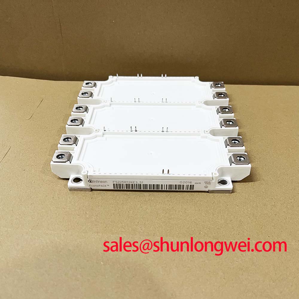
If an overvoltage alarm appears after a module change, compare the DC link waveform with a known working assembly and inspect the external suppression network. A metal oxide varistor, where fitted in the equipment, serves a different role from a local switching snubber: its coordination depends on the actual bus and surge conditions. Do not treat the presence of either part as proof that the module terminals remain within their limits. For another Infineon module under consideration, FS225R12KE3 is a comparison point, not an automatic replacement; confirm terminal arrangement, mounting, drive requirements and operating limits against the original assembly.
Field Diagnostics and Commissioning: Thermal Feedback in FS225R12KE4 Topologies
Probe the gate to emitter waveform at the installed module when parallel paths show unequal current or one heatsink area runs warmer. First establish the terminal identification from the equipment schematic and the applicable module documentation; the Module package designation does not define a pinout. Trace each gate connection back to its driver, inspect the return path, and compare waveforms at equivalent operating points. Differences in wiring length, connection resistance or stray inductance can affect switching balance even when the commanded signals look identical at the driver board.
A positive temperature coefficient of on state voltage can assist static current sharing under some operating conditions, but it must not be assumed across every current and temperature range for this specific part. As a Design Consideration, compare steady current and case temperature across parallel positions after thermal stabilization. Then inspect dynamic current sharing separately with suitable current measurement equipment. Static balance cannot establish that turn on and turn off transients are balanced.
Review the busbar contact surfaces and fastening method when a thermal image shows a localized hot terminal. Contact resistance, cooling airflow and thermal interface condition are all plausible contributors, so isolate the cause through inspection and comparative measurements rather than assigning it from one image. Verify the equipment specified fastening procedure and recheck accessible connections during scheduled maintenance. Maintenance Note: Isolate and discharge the equipment before checking terminal tightness or disturbing a module connection.
Clear dust from the heatsink and confirm that the intended airflow reaches its fins. Inspect the thermal interface for drying, displacement or uneven contact whenever the module is removed; apply replacement material according to the assembly procedure rather than assuming a universal layer thickness. In humid or cold installations, examine the enclosure for condensation and address the environmental control before returning the drive to service. These checks matter when evaluating an electric material handling drive, including a forklift traction inverter, but compatibility still depends on the actual electrical and mechanical design.
During a wider power stage review, BSM400GA120DN2S_E3256 may appear among components being evaluated for the system topology. Its name is not evidence of electrical or mechanical interchangeability with FS225R12KE4. Keep the driver supply, protection circuit and each device’s ratings tied to the position shown on the equipment schematic.
Field Diagnostics and Commissioning: Transient Thermal Response of FS225R12KE4
Record current, pulse duration and case temperature when an overload trip repeats after the heatsink appears to have cooled. The 225 A Official Specification is not a complete description of permissible pulsed operation. Junction temperature responds to both power loss and the time available for heat to move through the module and cooling assembly. A case sensor can therefore miss a short junction temperature peak.
For a pulsed load assessment, use the applicable transient thermal impedance information and loss characteristics for the device, together with the measured current waveform and cooling conditions. A multi stage thermal model can represent how heat flows over different timescales, but a credible peak junction temperature result requires the model coefficients and operating data. Those inputs are not supplied by the voltage, current and package specifications alone, so no peak temperature margin or recovery interval can be assigned here.
Examine the event sequence before increasing any overload setting. Compare the trip timestamp with current feedback, DC bus behavior, cooling fan operation and recent production load changes. If repeated pulses arrive before the assembly has thermally recovered, assess their combined effect rather than treating each pulse as an isolated event. When a semiconductor fuse is part of the equipment, coordinate its clearing behavior with the fault current path and the device protection design; a fuse current rating by itself does not establish protection of the IGBT during a hard short circuit.
Likewise, a surge current rating marked elsewhere in a power assembly cannot be transferred to this module without the appropriate device specification. Keep rectifier surge capability, fuse energy withstand and IGBT fault behavior as separate checks. For a structured inspection record covering measurements, fault observations and preventive work, the Field Engineer’s Handbook provides a broader troubleshooting reference. Record the conditions under which each reading was taken so that a later maintenance team can reproduce it.
Assembly Integrity and Layout Architecture: Fault Clearing Dynamics for FS225R12KE4
Capture the collector to emitter and gate to emitter waveforms during a controlled protection test if the drive reports a desaturation fault. Determine whether the fault begins at turn on, during conduction or during turn off; those observations lead to different checks. Inspect the driver supply, desaturation sensing path, gate connections and DC link before attributing the event to the module. The supplied FS225R12KE4 specifications do not state a short circuit withstand time or prescribe a detection threshold, so neither can be selected from its 1200 V and 225 A ratings.
Review the protection sequence on the equipment schematic. A staged gate turn off can limit the rate of current change during fault clearing, while excessive delay can increase device stress. As a Design Consideration, verify both the clearing behavior and the resulting collector voltage peak on the assembled power stage, using the applicable device and driver limits. Avoid assigning a universal clearing deadline to this module without a supported short circuit specification.
Inspect gate loop routing when the captured trace shows ringing or an unexpected rise of gate voltage during the opposite switch’s transition. Coupling through the device’s reverse transfer capacitance and the external wiring can influence that waveform; an active clamp, if present in the driver design, must be assessed in the context of the measured transient. Keep the gate and return paths controlled, then validate damping and clamp behavior under the equipment’s operating conditions. Infineon’s OptiMOS low voltage MOSFET information concerns a different device category and should not be used as a source of IGBT gate or fault limits for FS225R12KE4.
After a fault clearing test, check for loose busbar hardware, shifted insulating barriers and new hot spots before repeating a powered run. Confirm that protection trips consistently and that the measured turn off peak remains within the verified device operating boundary. If the observations change as the assembly warms, document the temperature and load alongside each waveform; those conditions are essential to deciding whether the driver, connection or cooling path needs further work.