



Content last revised on August 28, 2026
FZ1200R17KF4C High-Power IGBT Module: Thermal Optimization for Extreme Duty Cycles
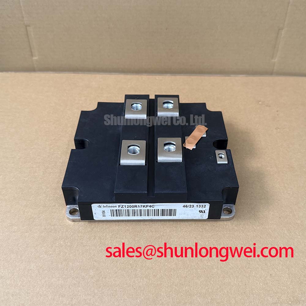
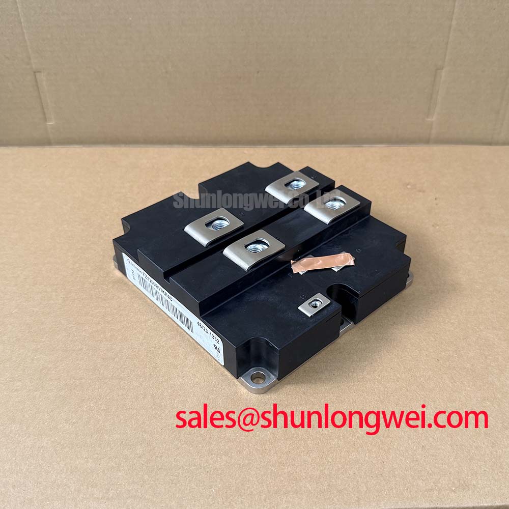
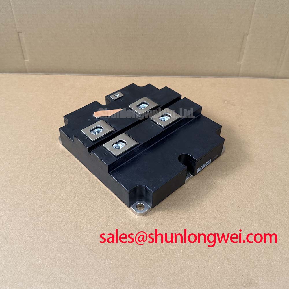
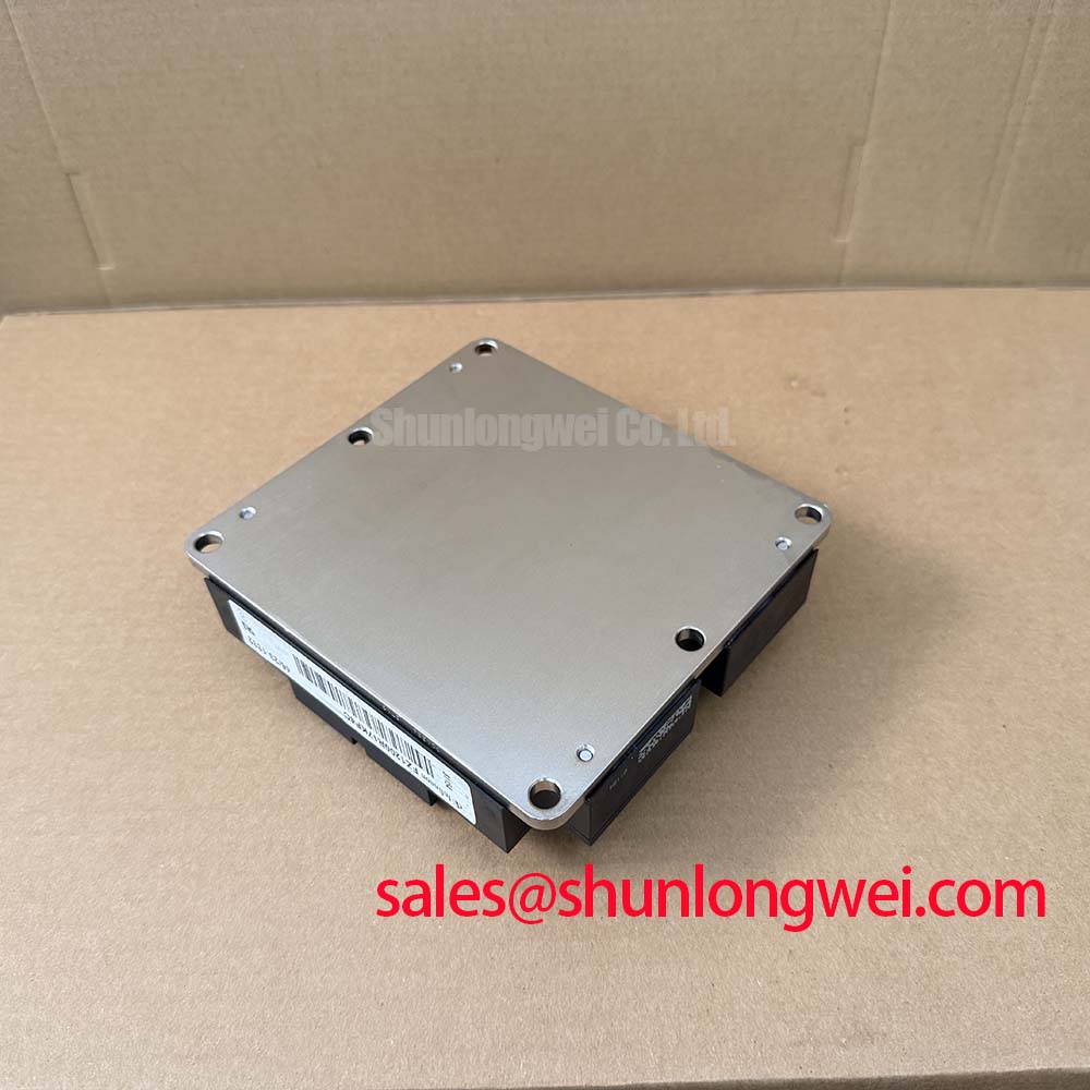
The FZ1200R17KF4C is a high-power single-switch IGBT module from Infineon designed to manage severe electrical and thermal stresses in heavy-duty converters. For 690V industrial line systems prioritizing thermal performance, this 1700V module is the optimal choice.
Key Specs: 1700V | 1200A | Rth(j-c) 0.016 K/W
Benefits: Minimizes heatsink volume; extends system lifetime under high load.
How does it prevent thermal runaway? The extremely low thermal resistance from junction to case ensures rapid heat dissipation, preventing thermal buildup that leads to silicon breakdown.
Quick Reference:
Q: What is the maximum continuous current? A: It supports up to 1200A at an 80 °C case temperature.
Q: What is the junction-to-case thermal resistance? A: The transistor's Rth(j-c) is rated at 0.016 K/W.
Key Parameter Overview
Decoding the Specs for Enhanced Thermal Reliability
| Maximum Rated Values | ||
|---|---|---|
| Collector-Emitter Voltage | VCES | 1700 V (Tvj = 25 °C) |
| Continuous DC Collector Current | IC | 1200 A (Tc = 80 °C) |
| Repetitive Peak Collector Current | ICRM | 2400 A (tp = 1 ms) |
| Total Power Dissipation | Ptot | 7800 W (Tc = 25 °C, Transistor) |
| Gate-Emitter Peak Voltage | VGE | ± 20 V |
| IGBT Characteristics | ||
| Collector-Emitter Saturation Voltage | VCE(sat) | 3.5 V (typ) / 3.9 V (max) @ 1200A, 25 °C 4.6 V (typ) / 5.0 V (max) @ 1200A, 125 °C |
| Gate Threshold Voltage | VGE(th) | 4.5 V (min) / 5.5 V (typ) / 6.5 V (max) |
| Input Capacitance | Cies | 180 nF (f = 1 MHz, VCE = 25 V) |
| Thermal & Mechanical Properties | ||
| Thermal Resistance (Junction-to-Case) | Rth(j-c) | 0.016 K/W (Transistor, DC) 0.040 K/W (Diode, DC) |
| Thermal Resistance (Case-to-Heatsink) | Rth(c-h) | 0.008 K/W (per module, conductive paste) |
| Max Junction Temperature | Tvj(max) | 150 °C |
| Mounting Torque (Mechanical) | M1 | 3 Nm (terminals M6) |
| Terminal Connection Torque | M2 | 8 to 10 Nm (terminals M8) |
Download the FZ1200R17KF4C datasheet for detailed specifications and performance curves.
Application Scenarios & Value
Achieving System-Level Benefits in High-Frequency Power Conversion
Industrial design engineers face critical challenges when sizing power semiconductors for severe application conditions like rolling mill motor drives, heavy traction converters, and megawatt-scale grid-tie installations. In these environments, transient load fluctuations and start-up surges are common. The FZ1200R17KF4C addresses these demands by offering a massive continuous DC current rating of 1200A and a peak current capability of 2400A. This headroom is vital for managing startup inrush currents without triggering premature thermal shutdown or desaturation faults.
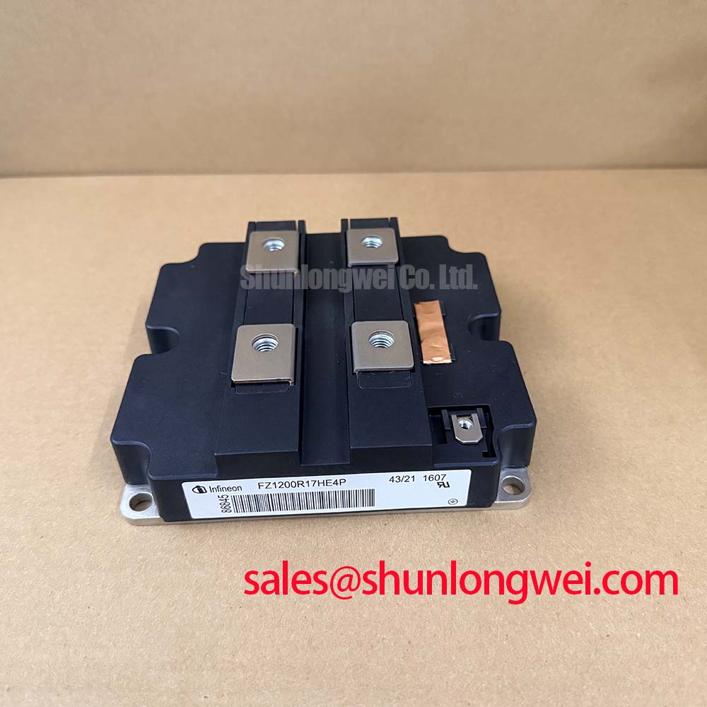
In massive installations, such as wind-to-grid conversion systems, this module operates at high duty cycles under variable ambient temperatures. Solder fatigue and thermal mismatch can degrade typical switches, but the rugged IHM-B package isolates the silicon from environmental degradation. For designs requiring an upgrade in switching losses or newer silicon structures, the FZ1200R17HE4 offers an alternative, whereas the FZ1200R17KF6C_B2 provides different diode characteristics to meet specialized electromagnetic compatibility standards.
Technical Deep Dive
A Closer Look at the Thermal Mechanics and Switching Capabilities
To fully grasp the operating boundary of the FZ1200R17KF4C, engineers must analyze the correlation between its electrical design and thermal management limits. Operating at a high continuous current of 1200A generates substantial heat due to the collector-emitter saturation voltage (VCE(sat)), which rises from a typical 3.5 V at room temperature to 4.6 V at the maximum operating temperature of 125 °C. In power electronics, this temperature-dependent increase in VCE(sat) acts like a toll booth on a busy highway: as the current flows, the voltage drop acts as a toll that converts electrical energy into heat.
To prevent catastrophic failure, this heat must be evacuated. Here, the module’s low thermal resistance (Rth(j-c)) of 0.016 K/W plays a critical role. Think of this thermal pathway as a multi-lane highway for heat; the low resistance means thermal energy is transferred out of the silicon junction to the copper baseplate with minimal impedance, keeping the junction temperature stable even during high-frequency switching operations. Designers can reference detailed guidelines in the failure analysis and reliability handbook to optimize heatsink mounting torque, ensuring the contact thermal resistance (Rth(c-h)) remains at its nominal 0.008 K/W.
Industry Insights & Strategic Advantage
Positioning the Legacy IHM Platform in Modern Grid Designs
As grid-tie systems and heavy industrial drives transition toward higher efficiency standards, selecting legacy platforms like the FZ1200R17KF4C requires a clear understanding of the trade-offs between switching speeds and system robustness. Modern silicon architectures prioritize lower switching losses but sometimes compromise on short-circuit ruggedness. This module, built on a mature planar technology, offers a robust design that provides a predictable Short-Circuit Withstand Time, allowing safety circuits to detect and isolate faults before damage occurs.
From a procurement and lifecycle planning perspective, maintaining equipment that utilizes this IHM-B packaged IGBT Module is vital for minimizing total cost of ownership. Retrofitting existing drives with newer generation modules often requires redesigning busbars and gate drivers. Utilizing a drop-in replacement that adheres to the original mechanical specifications ensures that legacy systems meet modern grid codes and safety requirements. Engineers seeking deeper insights on system design can consult the IGBT selection and system reliability guide to evaluate long-term deployment strategies.
Frequently Asked Questions
Common Technical Inquiries Addressed by Application Specialists
How does the Rth(j-c) value of 0.016 K/W for the FZ1200R17KF4C affect heatsink sizing in a 100 kW motor drive?
A low junction-to-case thermal resistance (Rth(j-c)) of 0.016 K/W minimizes the temperature gradient between the IGBT junction and the case. This allows designers to use a smaller, less expensive heatsink while maintaining the junction temperature below the maximum limit of 150 °C under heavy continuous loads.
Why does the VCE(sat) of this module increase to 4.6 V at 125 °C, and how should driver circuits be configured to handle it?
The positive temperature coefficient of VCE(sat) (increasing from 3.5 V at 25 °C to 4.6 V at 125 °C) is a characteristic of planar N-channel IGBTs. This makes the module highly suitable for paralleling since it naturally balances current distribution. Gate drive circuits should be configured with a stable VGE of 15 V to ensure full saturation and prevent thermal runaway under elevated operating temperatures.
To request technical pricing or verify lead times for the FZ1200R17KF4C, contact our global sales team or submit an inquiry online. Our application engineers are available to support your evaluation of legacy power semiconductor modules.