Content last revised on September 10, 2026
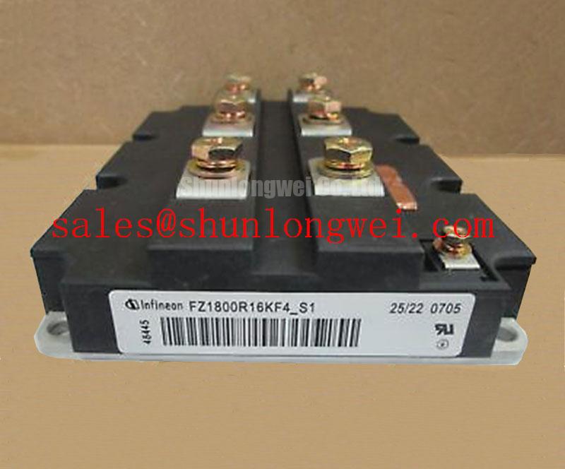
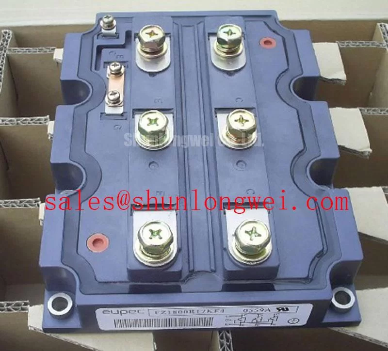
FZ1800R16KF4 Infineon Single IGBT Module: Technical Analysis & Power Stage Integration
UVP: Delivering robust 1600V/1800A single-switch capability for heavy industrial inverters and megawatt power conversion.
Core Specs: 1600V VCES | 1800A IC | 3.4 kV VISOL
Key Benefits: High current handling in a standard high-power footprint; enhanced insulation withstand for industrial utility grids.
Does the 1600V blocking rating provide sufficient headroom for 690V AC industrial lines? Yes, 1600V collector-emitter voltage provides a reliable voltage safety margin against DC link surges in rectified 690V line operations.
For multi-megawatt traction drives and grid converters requiring high surge margins, the FZ1800R16KF4 delivers dependable switching capacity.
Application Scenarios & Value
Bridging High Current Density and Electrical Margin in Grid-Tied Systems
Engineers often face severe design trade-offs when developing multi-megawatt converter topologies. Balancing conduction losses against transient voltage spikes in high-current paths requires substantial semiconductor headroom. In heavy-duty variable frequency drives and wind power conversion systems, DC-link voltages frequently hover near 900V to 1000V during regenerative braking or grid fluctuation events.
The FZ1800R16KF4 addresses this operational boundary by pairing a 1600V collector-emitter rating with an 1800A continuous DC collector current. Think of this voltage rating like an expansive spillway on a high-capacity dam; it absorbs sudden operational surges without breaching silicon breakdown limits.
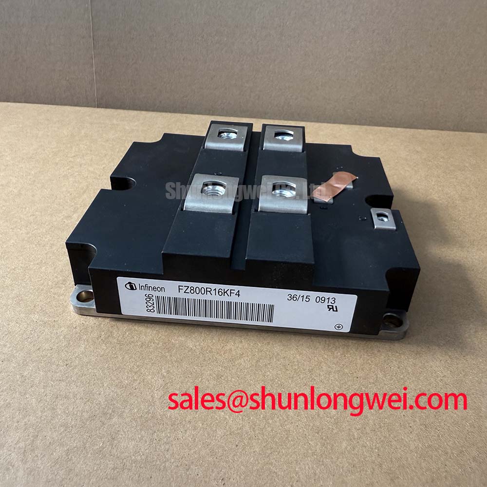
In high-power industrial converters, designers frequently evaluate alternative current steps. While this module accommodates 1800A single-switch configurations, designers evaluating lower current thresholds in the same class can review the related FZ1200R16KF4, or examine the 1200V alternative FZ1800R12KF4 when lower DC-bus voltages are utilized. For systems requiring specific manufacturing revisions, the variant FZ1800R16KF4_S1 is also documented in the series.
Integrating these high-capacity IGBT modules into central inverters ensures compliance with demanding grid codes while maintaining stable thermal boundaries.
Technical Deep Dive
Internal Architecture, Dynamic Behavior, and Paralleling Dynamics
What is the primary role of the integrated freewheeling diode? It provides low-loss inductive energy recirculation while clamping inductive kickback spikes.
The internal construction of the Infineon FZ1800R16KF4 utilizes planar IGBT chips paired with fast-recovery freewheeling diodes mounted on an electrically isolated, high-conductivity baseplate. Managing thermal expansion across multi-chip layouts requires stable mechanical joints. The thermal interface acts much like the suspension system of an articulated truck, absorbing mechanical stresses caused by continuous thermal expansion cycles during heavy load swings.
Implementing successful IGBT paralleling schemes requires tight gate synchronization and symmetrical busbar geometries. Stray inductances in the power loops must be minimized to ensure dynamic current sharing across parallel modules and keep switching spikes well within the SOA (Safe Operating Area).
Careful gate drive design with active clamping protects the gate-emitter oxide from overvoltage while maintaining clean transition rates during hard-switching sequences. Proper thermal management and symmetrical heatsink clamping ensure uniform temperature distribution across all internal semiconductor dies.
Key Parameter Overview
Critical Specifications and Engineering Value Interpretation
| Parameter Symbol | Technical Specification | Engineering Value & Design Impact |
|---|---|---|
| VCES | 1600V | Allows stable operation on 690V AC rectified lines with high surge margins. |
| IC | 1800A (Continuous DC) | Enables megawatt-level power conversion with minimal parallel module count. |
| ICRM | 3600A (Repetitive Peak) | Provides overload capability during motor startup transients and fault conditions. |
| VCE(sat) | 3.5V (typ. @ 25°C, 1.8 kA) | Determines steady-state conduction loss profiles in heavy-load conversion stages. |
| VISOL | 3.4 kV (RMS, 50 Hz, 1 min) | Ensures robust galvanic safety isolation between power silicon and baseplate. |
| Ptot | 11 kW (Max Dissipation @ TC=25°C) | Sets total heat extraction limits required for liquid or forced-air heatsink sizing. |
Download the FZ1800R16KF4 datasheet for detailed specifications and performance curves.
Frequently Asked Questions
Engineering Queries and Integration Factors
What makes the 1600V rating advantageous over standard 1200V modules in 690V line inverters?
A 690V AC line rectified to DC creates nominal bus voltages near 950V to 1000V. A 1200V switch leaves narrow safety headroom against inductive switching spikes, whereas a 1600V device provides ample buffer to prevent avalanche breakdown.
What is the maximum repetitive peak collector current (ICRM) of the FZ1800R16KF4?
The repetitive peak collector current is rated at 3600A for 1 ms pulse durations, accommodating short-term motor starting torque demands and dynamic grid disturbances.
How does isolation test voltage (VISOL) impact mechanical layout in converter cabinets?
With a 3.4 kV RMS insulation test rating, the module complies with industrial dielectric requirements, allowing multiple switches to share a common grounded heatsink without external insulation barriers.
Why is symmetrical DC busbar design critical when operating at 1800A continuous current?
High continuous currents generate significant inductive loop voltage spikes (V = L × di/dt). Symmetrical low-inductance busbars prevent uneven dynamic current sharing and suppress collector-emitter voltage overshoots during turn-off.
What gate voltage levels are recommended for driving the FZ1800R16KF4?
Standard gate drive voltages of +15V for turn-on and -5V to -15V for turn-off provide full saturation, minimize conduction losses, and prevent parasitic Miller turn-on during high dv/dt transients.
From an engineering perspective, evaluating the FZ1800R16KF4 involves balancing thermal dissipation, loop inductance, and switching frequency to optimize the total system efficiency of high-power converters.