Content last revised on March 16, 2026
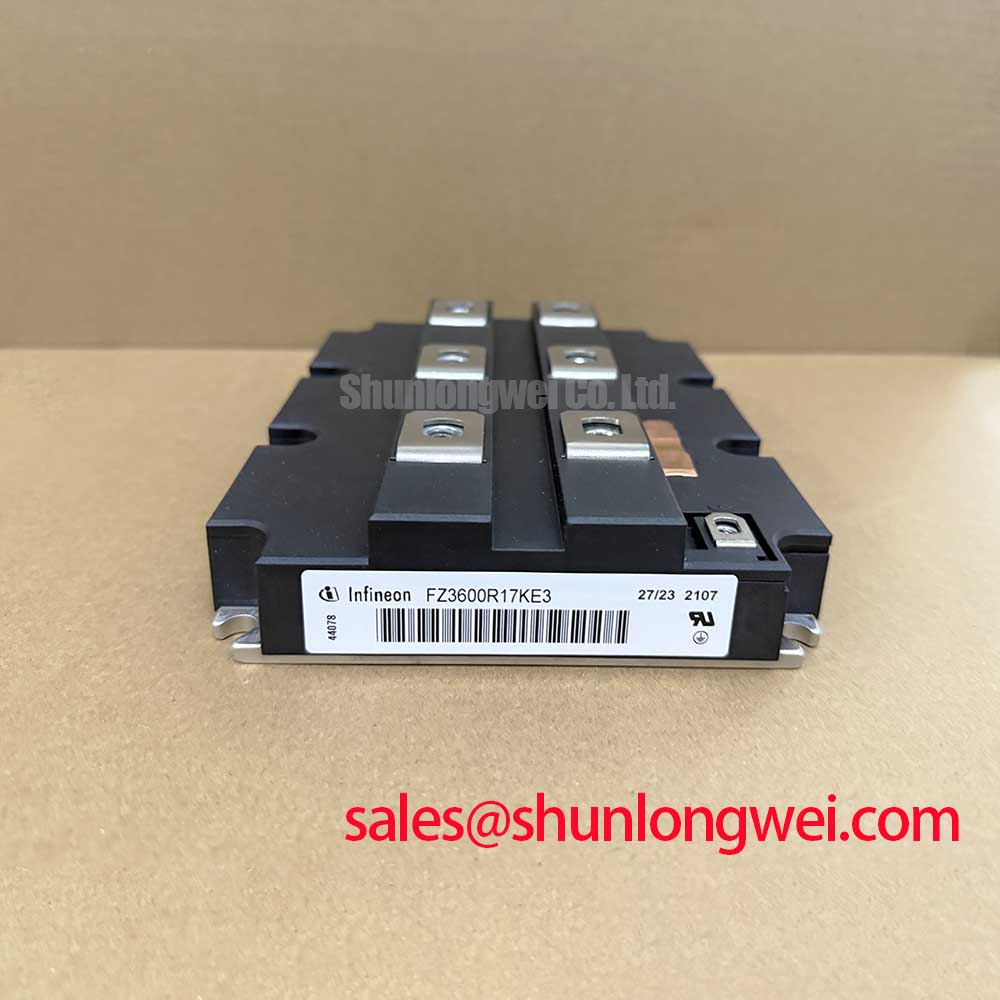
FZ2400R12KF4 Infineon IGBT Module 1200V 2400A IHM-B Engineering Overview
The FZ2400R12KF4 represents a pinnacle in high-power semiconductor engineering, designed by Infineon to meet the rigorous demands of megawatt-scale power conversion systems. As a single IGBT module housed in the industry-standard IHM-B package, it offers a formidable 1200V collector-emitter voltage and a continuous DC collector current of 2400A. This module is specifically optimized for applications where thermal robustness and long-term reliability are non-negotiable, such as heavy industrial drives and renewable energy grid-ties.
For engineers prioritizing high-power density and thermal stability in 1200V architectures, the FZ2400R12KF4 serves as a critical building block for high-efficiency inverter stages. By leveraging a large-area isolated copper baseplate, the module minimizes internal thermal resistance, allowing for superior heat dissipation under extreme load cycles. Its electrical ruggedness is further characterized by a high short-circuit withstand time and a wide square reverse bias safe operating area (RBSOA). For 400V–690V AC grid-connected systems requiring maximum current handling in a compact footprint, the FZ2400R12KF4 is the optimal choice.
Key Parameter Overview
Decoding the Specs for MW-Scale Power Reliability
The following technical specifications define the operating envelope of the FZ2400R12KF4. These values are derived from the official Infineon documentation to ensure precision in your system-level calculations.
| Technical Parameter | Official Specification Value | Engineering Significance |
|---|---|---|
| Collector-Emitter Voltage (Vces) | 1200V | Provides safety margin for 400V-690V AC line applications. |
| Continuous DC Collector Current (Ic) | 2400A | Enables high-power throughput in single-switch configurations. |
| Repetitive Peak Collector Current (Icrm) | 4800A | Critical for handling transient surges and motor startup loads. |
| Total Power Dissipation (Ptot) | 18.0 kW | Indicates the maximum heat energy the module can reject at Tc=25°C. |
| Isolation Test Voltage (Visol) | 2.5 kV (RMS, f=50Hz, t=1min) | Ensures safe galvanic isolation between the power circuit and heatsink. |
| Package Type | IHM-B (190mm) | Standard footprint for easy integration into existing busbar designs. |
Download the FZ2400R12KF4 datasheet for detailed specifications and performance curves.
Application Scenarios & Value
Engineered for High-Power Density in Industrial Converters
Engineers often face the challenge of maintaining thermal equilibrium in high-current density environments. The FZ2400R12KF4 addresses this by offering one of the highest current ratings available in the 1200V class. In a typical Variable Frequency Drive (VFD) application for mining or marine propulsion, the module's 2400A rating allows designers to reduce the number of paralleled components, thereby simplifying busbar layout and reducing parasitic inductance.
In the realm of Renewable Energy, specifically for central wind power inverters, the module's ability to withstand frequent power cycling is paramount. The integration of high-performance freewheeling diodes with low reverse recovery charges ensures that switching losses are kept at a minimum even during high-frequency operation. For systems requiring even more advanced thermal performance or newer chip technology in a similar footprint, the FZ2400R12HP4 offers a high-speed trench-field-stop alternative, while the FZ1200R12KF5 provides a lower current alternative for modular designs.
The FZ2400R12KF4 is also widely utilized in UPS (Uninterruptible Power Supply) systems for data centers, where its high Icrm rating of 4800A ensures the system can handle significant inrush currents without triggering protective desaturation. To better understand how these components integrate into larger systems, refer to our guide on IGBT modules in high-efficiency power systems.
Technical Deep Dive
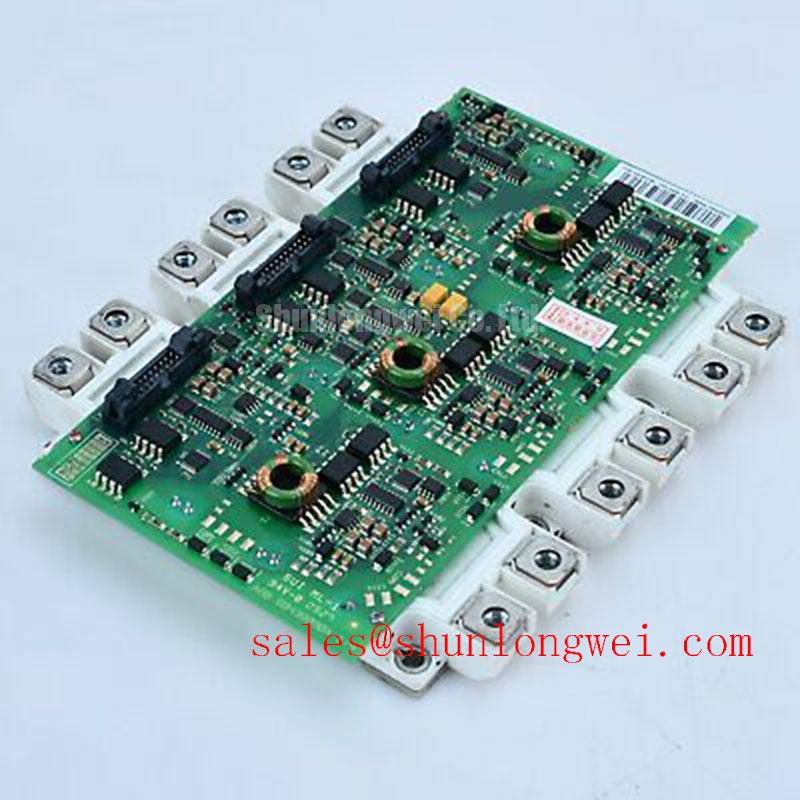
Inside the IHM-B Package: Optimizing Thermal Conductivity and Reliability
The mechanical architecture of the FZ2400R12KF4 is as vital as its electrical performance. The IHM-B housing utilizes a pressure-contact-like internal structure for internal connections, though the baseplate itself is traditionally soldered to the substrate. The use of AlSiC (Aluminum Silicon Carbide) or optimized copper baseplates significantly reduces the coefficient of thermal expansion (CTE) mismatch between the silicon die and the module housing. This is analogous to the suspension system in a heavy-duty truck; just as a suspension absorbs road shock to protect the cargo, the optimized internal stacking of the FZ2400R12KF4 absorbs the "thermal shock" of rapid power cycles, preventing micro-cracks in the solder layers.
From a Gate Drive perspective, the module's input capacitance is significant due to its 2400A die area. Engineers must select a driver capable of providing sufficient peak gate current to avoid slow switching transitions, which would otherwise escalate switching losses (Eon/Eoff). Implementing a Miller Clamp is highly recommended in these high-current environments to prevent parasitic turn-on caused by high dv/dt transients. For further insights on preventing catastrophic failures, consult our technical resource on IGBT failure analysis and prevention. Additionally, understanding the physics and structure of IGBTs can provide a deeper appreciation for the FZ2400R12KF4's internal design.
Frequently Asked Questions
How does the thermal resistance Rth(j-c) of the FZ2400R12KF4 impact heatsink selection?
The thermal resistance from junction to case (Rthjc) is a critical bottleneck in the heat flow path. For the FZ2400R12KF4, this value is kept extremely low to allow the 2400A current to flow without exceeding the 150°C maximum junction temperature. This necessitates a high-performance liquid-cooling system or a very large forced-air heatsink to ensure the case temperature (Tc) remains within safe limits during continuous operation.
What is the primary benefit of the IHM-B package for this 1200V module?
The IHM-B package provides an standardized, robust footprint that supports high-current busbar connections through multiple M8 terminals. This reduces current crowding and localized heating, ensuring that the 2400A load is distributed evenly across the internal parallel dies, enhancing long-term reliability by eliminating localized thermal stress points.
Can the FZ2400R12KF4 be used in 690V AC line applications?
Yes. With a Vces of 1200V, the module provides a sufficient safety margin for the peak voltages encountered in 690V RMS systems (approximately 975V peak), allowing for standard DC bus voltages up to 800V-900V while leaving room for inductive voltage spikes during switching. For even higher voltage overhead, engineers often look to 1700V modules like those discussed in our industrial application topics.
As a specialized distributor, we provide the technical data necessary for engineers to integrate the FZ2400R12KF4 into high-reliability power systems. Our focus is on providing the engineering transparency required for successful Thermal Management and System Integration. For technical support regarding Gate Drive requirements or busbar optimization for this Infineon IGBT Module, please consult our engineering team.