

Content last revised on October 13, 2026
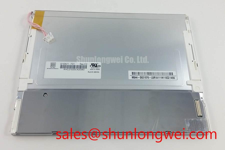
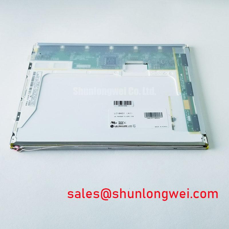
LC104S1-A1 LG Display Industrial TFT LCD Panel
When a marine radar console reports a blank quadrant, uneven illumination, or intermittent image loss, isolate the display assembly before changing the controller: inspect the panel connector, check the flex cable for parallel insertion, and run a controlled full-screen color test. The LC104S1-A1 is identified as an LG Display TFT-LCD active matrix color display module for industrial LCD and HMI equipment. Its supplied product classification is Industrial Grade LCD/HMI Panel, with a Decoded Baseline / Standard Form Factor specification status.
The available product identity does not establish a universal operating voltage, signal standard, backlight architecture, optical coating, touch function, or mechanical dimension. Those values must match the original panel documentation and the host equipment wiring. For a replacement in a harsh marine radar or navigation bridge console, compare the complete assembly interface, mounting position, display timing, backlight driver arrangement, and environmental sealing before installation.
Industrial TFT operating principles are described in the Winstar industrial TFT-LCD and OLED display reference, while the pixel switching structure is outlined in this TFT LCD technology overview. These references support general display engineering context and do not replace the original panel documentation for this model.
Controlled 100-Ohm Differential Impedance Flex Routing to Suppress High-Frequency Jitter
Start signal-integrity work by identifying the host controller output format and matching it to the original panel pinout. A 100-ohm differential routing target is a Design Consideration for a differential display link, not an official LC104S1-A1 parameter. If the equipment uses a differential interface, route each pair with consistent geometry, avoid unnecessary branch stubs, and keep the return path continuous through the flex and connector transition.
Split-screen artifacts, unstable vertical regions, or repeated image fragments can develop from timing mismatch, pair imbalance, connector contamination, or incorrect data mapping. Compare the replacement panel against a known-good signal path with an oscilloscope, checking clock relationship, pair activity, and startup behavior. JEIDA and VESA mappings are not interchangeable assumptions; the system integrator should verify the required mapping from the original controller documentation.
Power sequencing also belongs to the host-system validation plan. Verify the actual logic rail, enable order, reset behavior, and panel-ready timing used by the equipment rather than applying a generic supply value. The same discipline applies when evaluating a related display path such as NL8060BC31-42; its role should be assessed from the system schematic and connector arrangement, not from physical similarity alone.
Servo drives and switching supplies near a display cable can inject common-mode interference into long flex routes. A practical Design Consideration is to separate high-current switching conductors from the display harness and confirm image stability while the machine passes through its highest-noise operating states. EMC performance belongs to the completed equipment, so the panel itself should not be represented as independently certified to a system-level EMC standard.
High-Humidity Storage Margins and Delamination Prevention Protocols
Humidity screening should begin with the panel perimeter, connector interface, exposed flex region, and front surface. Look for lifting edges, haze, trapped contamination, or changes that appear after controlled temperature transitions. The LC104S1-A1 listing identifies the display category and construction class, but it does not establish a model-specific qualification curve for storage at 60°C and 90% relative humidity.
Sub-zero operation can increase liquid-crystal response lag and make moving graphics appear less responsive. This is a general LCD behavior and should be evaluated with the actual controller timing, image content, and enclosure temperature. A gray-to-gray response check is more useful than a static color screen when assessing motion trails, cursor movement, or radar sweep presentation.
Thermal cycling from low temperature toward elevated temperature can create condensation risk at the equipment level. Use a controlled transition procedure, allow the assembly to equalize before applying power, and inspect the seal perimeter after cycling. Do not infer adhesive, sealant, polarizer, or light-guide materials from the TFT-LCD classification alone. The enclosure designer remains responsible for marine sealing, salt exposure control, and internal moisture management.
For replacement planning, compare the original panel’s bezel, mounting pressure, cable bend path, and ventilation clearance. Excessive local pressure can distort the viewing area even when the electrical connection is correct. A neutral compatibility reference is NL6448BC33-71, which may be reviewed as a separate same-class display option only after resolution, connector, timing, and mechanical compatibility are confirmed.
Full-Screen Primary Color AOI Screening: Stuck Sub-Pixels and Background Uniformity Audit
Run the incoming inspection with full-screen red, green, blue, white, black, and mid-gray images. Keep the viewing angle fixed and inspect the active area for stuck sub-pixels, line defects, bright points, dark points, mura, and nonuniform background illumination. Record the defect position relative to the panel edges so that a repeat inspection can distinguish a stable pixel defect from a temporary cable or controller fault.
A 45-degree flashlight inspection is useful when the display is dark. Sweep the light across the surface and edges to separate a backlight shadow from a signal-line defect. A shadow that changes with illumination angle may involve the optical or mechanical stack, while a fixed line or column artifact should be compared with the controller output and flex seating. This test is a diagnostic aid, not a model-specific acceptance limit.
Backlight uniformity should be checked at several brightness settings, with the panel warmed to its normal operating condition. If a PWM dimming method is used by the equipment, inspect duty-cycle behavior and visual flicker across the intended control range. The commonly evaluated 200 Hz to 1 kHz region is a Design Consideration for system testing, not a confirmed specification of the LC104S1-A1.
💡 Bench Tip: Use ESD protection and lock the flex cable only after the contacts are fully parallel and evenly seated; powering the display while the cable is skewed can complicate later fault isolation.
Backlight Architecture, Constant-Current Driving, PWM Dimming, and Flicker Suppression
Identify the installed backlight architecture before connecting a replacement driver. The supplied LC104S1-A1 product data classifies the unit as a TFT-LCD active matrix color display module but does not confirm whether a particular assembly uses WLED, CCFL, an integrated driver, or an external backlight controller. The equipment schematic and original panel documentation must define the required current, voltage, enable signal, dimming method, and connector pinout.
When a constant-current LED driver is present, evaluate brightness stability, startup behavior, current regulation, thermal distribution, and visible flicker across the system’s normal control range. A 1000:1 PWM dimming ratio is an application-level target that requires confirmation from the complete driver and panel combination; it should not be assigned to this model as an official factory rating.
Older equipment may use a high-voltage CCFL inverter, where ignition and operating conditions differ substantially from a solid-state LED driver. Do not connect one backlight topology to the other without a verified electrical interface. Audible noise, intermittent ignition, or uneven illumination should be investigated across the driver, harness, connector, and panel rather than attributed to the LCD module alone.
In high-EMI factory environments, differential pair routing should preserve controlled geometry and minimize skew through connectors and flex transitions. A 100-ohm ±10% target and a 50 ps skew budget can be used only as system-level engineering starting points when supported by the controller design and measurement method. Validate the actual image link with the installed harness, enclosure, and nearby servo equipment. Additional principles for display selection, signal integrity, and common integration errors are covered in The Ultimate Guide to Industrial TFT LCD Technology.