Content last revised on October 26, 2026
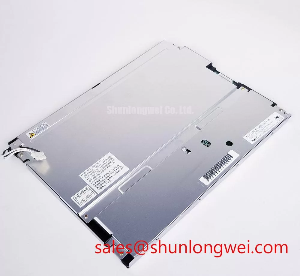
NEC NL6448BC33-46D Display Module Integration Checks
Check the panel connector, mounting aperture, and cold-start image path before applying power to a railway display assembly. The NL6448BC33-46D is a NEC TFT-LCD active matrix color display module. Electrical ratings, pin assignment, backlight drive method, optical limits, and mechanical dimensions must be matched with the applicable panel documentation before installation.
For repair and sourcing teams, this identity separates the display module from the surrounding driver board, backlight drive circuitry, cable harness, and enclosure. A replacement assessment should therefore compare the complete interface chain rather than relying on the model number alone. The intended equipment may include railway passenger information terminals, cab signalling displays, industrial HMI consoles, or operator panels, subject to verification of the module’s suitability for the application and the host system’s electrical, mechanical, environmental, and regulatory requirements.
Thermal Dissipation and Light Guide Preservation in Edge-Lit Backlight Assemblies
Thermal inspection around the narrow display edges should begin with the backlight assembly, not with assumptions about the LCD cell itself. If the host equipment uses an edge-lit LED structure and a polymer light guide, heat concentrated near the LED rail can create optical non-uniformity, local color shift, or gradual yellowing. Those conditions belong to the complete backlight and enclosure design; they are not established specifications of the NL6448BC33-46D identity.
A practical design consideration is to provide a mechanically stable heat-spreading path along the active backlight edge while keeping pressure away from the glass and optical stack. The spreader, bracket, gasket, and rear cover should be checked together because an apparently minor enclosure distortion can create uneven optical loading. Engineers evaluating this NEC panel for a railway information terminal should compare the original bezel depth, ventilation path, backlight driver location, and service clearance before adding any thermal hardware.
Where supported, PWM control belongs to the backlight driver. A system-level evaluation may examine a PWM window such as 200 Hz to 1 kHz when checking visible flicker, acoustic interaction, and camera-recorded modulation, but this is a design consideration rather than an NL6448BC33-46D factory rating. Duty-cycle linearity should be checked against measured luminance at the installed panel, especially where passenger information text changes between bright and dim operating modes. A brightness-life statement such as 50,000 hours must be attributed to the documented backlight assembly and its specified conditions, not automatically transferred to the LCD module.
Suppressing Pixel Jitter & Horizontal White Lines Induced by Adjacent 400V Motor Drives
When the display is installed near a 400 V variable-frequency motor drive, inspect the complete signal route from the controller to the panel before changing the display module. Pixel jitter and horizontal white bands can arise from cable coupling, reference-potential movement, connector contact variation, or timing disturbance. The useful comparison is between the known-good signal path and the installed path under the same motor operating condition.
A shielded display cable appropriate to the documented interface should be routed away from high-current switching conductors, with its shield termination and chassis reference defined by the system grounding plan. A 360-degree shield connection can reduce exposed pigtail length, but its effectiveness depends on the enclosure, connector geometry, and bonding arrangement. Common-mode ferrite components may also be evaluated where measurements show conducted or radiated interference, although their impedance behavior must be checked across the actual signal spectrum rather than selected by appearance alone.
The display module should not be credited with independent EMC compliance for the complete railway or industrial assembly. The enclosure, cable routing, controller, backlight driver, grounding, and power conversion stages all influence the final result. For related display architecture research, engineers can consult The Ultimate Guide to Industrial TFT LCD Technology. Tianma Industrial Display Products can also provide broader industrial display context, while the NEC corporate website provides general company information.
Backlight brightness decay should be evaluated with the installed backlight driver, thermal condition, and duty profile. A claimed 50,000-hour operating figure, when present in system literature, should be treated according to its documented conditions and lifetime definition rather than as a guaranteed field result for this LCD module. Record luminance uniformity, startup behavior, and image stability at the actual cabinet temperature instead of assigning a single fault to the panel.
Evaluating Viewing Angles for Multi-Angle Consoles
Viewing-angle evaluation should be performed from the operator positions that matter, with the installed cover glass, anti-glare surface, ambient light, and display graphics all in place. TN, IPS, and MVA technologies can present different grayscale behavior and contrast changes at oblique angles, but a particular cell technology or an 85/85/85/85 viewing specification should not be assumed for the NL6448BC33-46D without confirmation from its documentation.
For a multi-angle cab console or passenger information terminal, inspect grayscale inversion, dark-scene readability, reflected lighting, and the visibility of fine status text from each approved viewing position. Surface treatment should be assessed with the real enclosure window because external glass, protective films, and air gaps can change glare and perceived contrast. An anti-glare finish may reduce reflections while also altering image sharpness, so the decision should be made using the actual user interface rather than a bare-panel observation.
Cold operation requires a separate response assessment. Liquid-crystal viscosity can increase as ambient temperature falls, extending gray-to-gray transitions and making moving text or symbols appear delayed during startup. If a system uses a heater or controlled enclosure temperature, its activation sequence should be evaluated with the panel power sequence and controller initialization. The temperature range and response limits must come from the applicable display documentation; they should not be inferred from the module’s form factor.
Mitigating Gray-to-Gray (GTG) Response Time Escalation during Cold-Start Machine Power-Up
Cold-start testing should capture the first usable image, transition behavior, and uniformity while the cabinet moves from storage temperature toward its operating condition, without powering the panel outside its specified operating range. Gray-to-gray response changes may be most visible in scrolling characters, diagonal symbols, and rapidly changing alarm screens. Engineers should distinguish a panel response characteristic from delays introduced by the host processor, frame buffer, display controller, or backlight enable sequence.
For high-interference installations that use an LVDS interface, the differential pair route should maintain consistent geometry, reference continuity, and controlled connector transitions. A commonly used LVDS design target is 100 Ω differential impedance, but the applicable impedance tolerance and skew limits must come from the interface documentation; this is not a confirmed factory specification for NL6448BC33-46D. The system engineer should validate the actual interface standard, signal polarity, data order, clock relationship, and power-up timing against the original panel documentation and controller design.
Mechanical replacement work should preserve the original bezel opening, display viewing position, cable bend path, and fastener loading. Excessive local pressure can create optical non-uniformity even when the electrical signals are correct. 💡 Pro Tip: Disconnect panel power before inserting or removing the display cable, then inspect the connector alignment under magnification before the next startup test.
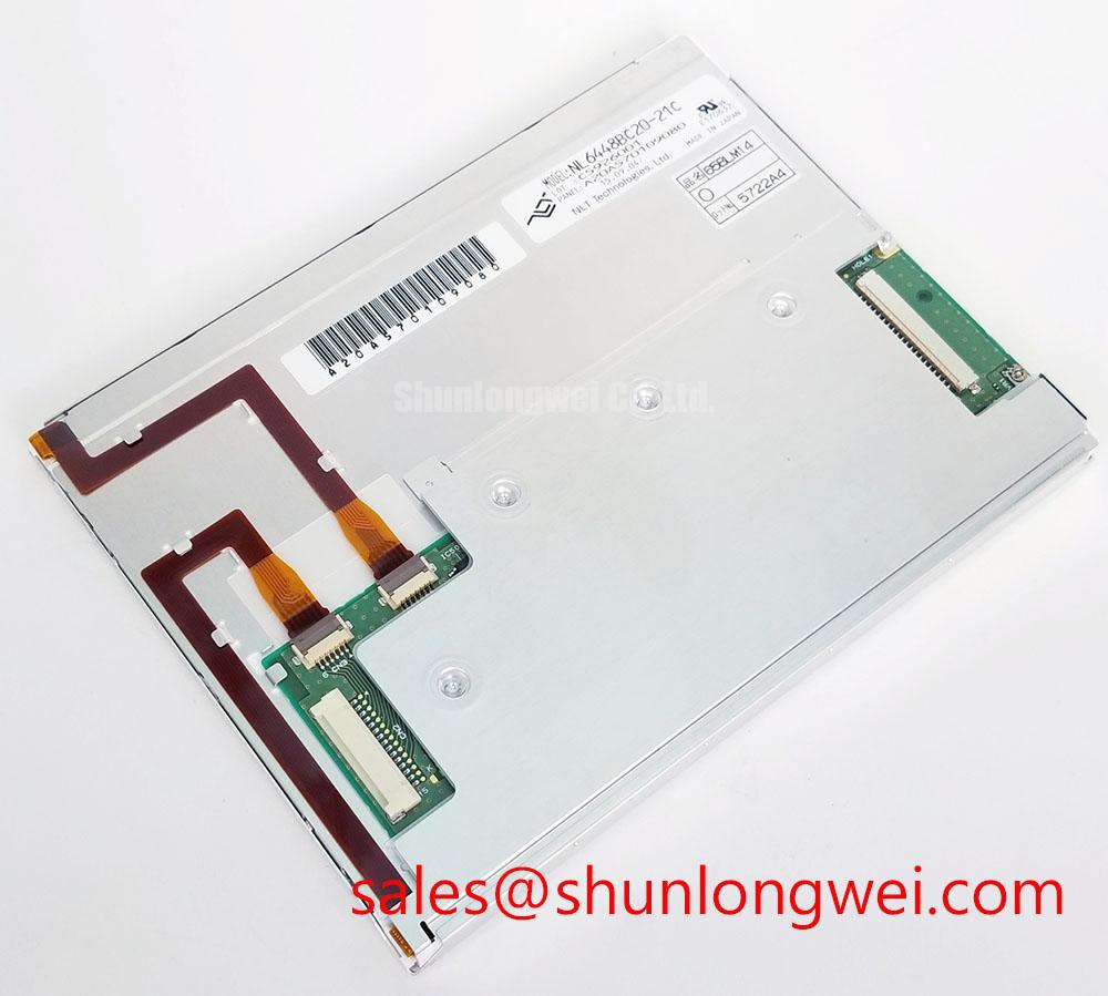
Where a direct replacement is unavailable, the NL6448BC33-71 can be reviewed as a separate same-family display option, but physical dimensions, interface timing, optical characteristics, and backlight requirements must be compared rather than assumed interchangeable. For another display module to research, engineers may also review NL8060BC31-42. The final selection remains dependent on measured system compatibility, controller configuration, enclosure geometry, and the documentation assigned to the installed equipment.