
Content last revised on September 10, 2026
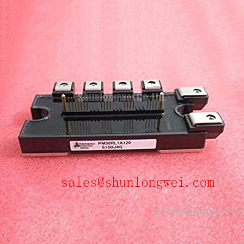
PM50RL1A120 Intelligent Power Module: Technical Specifications and Engineering Architecture
The PM50RL1A120 is an advanced 1200V, 50A 7-pack Intelligent Power Module (IPM) from the L1-Series, integrating 5th-generation Mitsubishi CSTBT™ (Carrier Stored Trench-gate Bipolar Transistor) technology with integrated gate-drive and multi-protection circuitry. Rated for 1200V collector-emitter voltage, 50A collector current, and an isolation rating of 2500Vrms, this integrated 7-pack topology streamlines three-phase motor drive inverter stages while incorporating a dedicated dynamic brake IGBT. By placing driver ICs and sensing circuits adjacent to the power dice, the module minimizes parasitic gate inductance and eliminates external driver layout complexity. For 400V–480V AC industrial motor drives requiring integrated dynamic braking, the 1200V 50A PM50RL1A120 delivers optimal design compactness and silicon protection.
What is the main advantage of the PM50RL1A120? It integrates gate drive and protection directly on-chip to maximize switching reliability and power density. How does integrated sensing protect the IGBT? On-chip real-time thermal and current monitors trigger soft-shutdown within microseconds during fault events.
Key Parameter Overview
Highlighting Critical Electrical, Thermal, and Protection Thresholds
A rigorous evaluation of power semiconductors requires understanding how conduction losses, isolation robustness, and thermal resistance align with operating margins. The table below presents the verified parameters for the PM50RL1A120 under standard test conditions.
| Key Parameter | Symbol | Rated Value / Condition | Engineering Significance |
|---|---|---|---|
| Collector-Emitter Voltage | VCES | 1200 V (Tj = 25°C) | Provides sufficient overhead for 400V/480V AC utility supply lines and regenerative surge events. |
| Collector Current (DC) | IC | 50 A (TC = 125°C) | Defines continuous current capacity for driving medium-power industrial induction and PM servo motors. |
| Collector-Emitter Saturation Voltage | VCE(sat) | 1.90 V (typ) / 2.45 V (max) (IC = 50A, VD = 15V, Tj = 125°C) | Ensures low forward conduction losses in high-duty-cycle industrial inverter drives. |
| Brake Collector Current (DC) | IC(Brake) | 25 A / 50 A peak | Dedicated internal chopper switch for absorbing kinetic energy during motor deceleration. |
| Thermal Resistance (Junction-to-Case) | Rth(j-c)Q | 0.27 °C/W (Inverter IGBT, per switch) | Enables efficient heat extraction from the silicon junction to the baseplate and heatsink assembly. |
| Isolation Voltage | Viso | 2500 Vrms (60 Hz, AC 1 min, baseplate to pins) | Ensures safety compliance and isolation between high-voltage bus and low-voltage control circuits. |
| Short-Circuit Protection Trip Level | ISC | 100 A (min) (Tj = 125°C) | Autonomous hardware-level overcurrent shutdown preventing catastrophic failure during phase-to-phase shorts. |
Download the PM50RL1A120 datasheet for detailed specifications and performance curves.
Application Scenarios & Value
Optimizing Motor Control and Dynamic Braking in Factory Automation
In modern industrial automation, engineers developing Variable Frequency Drive (VFD) systems and multi-axis servo drives frequently face spatial constraints and harsh electrical transients. Consider a 15 kW factory conveyor inverter operating on a 400V AC three-phase supply. During rapid emergency braking of high-inertia mechanical loads, bus voltages spike due to regenerative energy. The PM50RL1A120 resolves this challenge by combining a balanced 1200V collector-emitter rating with an integrated brake chopper circuit. The brake IGBT dynamically channels peak surge energy into external braking resistors, shielding the DC bus capacitors and the main inverter bridge from overvoltage degradation.
Furthermore, implementing this module eliminates the need for separate gate driver PCBs, optocoupler matching, and discrete temperature monitoring circuits. In high-vibration CNC machines and pump systems, utilizing an integrated IPM architecture reduces total component count by over 40%, directly lowering parasitic loop inductance and system assembly costs. For thermal management evaluations, matching the 0.27 °C/W junction-to-case thermal resistance with proper thermal interface materials (TIM) ensures junction temperatures (Tj) remain well below the 150°C maximum rating, adhering to IEC 61800-3 industrial standards.
For systems with standard six-pack topologies that do not require an integrated brake switch, the related PM50CL1A120 offers an identical 1200V 50A six-switch configuration. For installations demanding higher current throughput in a matching footprint, the related PM75RL1A120 provides an upgraded 75A rating.
Technical Deep Dive
Silicon Physics of CSTBT Architecture and Integrated Gate-Drive Protections
The core advantage of the PM50RL1A120 lies in the synergy between its Carrier Stored Trench-gate Bipolar Transistor (CSTBT) silicon structure and its internal control ICs. In conventional planar or trench IGBTs, optimizing trade-offs between forward conduction drop (VCE(sat)) and turn-off switching energy (Eoff) is fundamentally limited by carrier distribution near the emitter. CSTBT technology introduces a buried layer that accumulates high carrier concentration near the surface. To visualize this mechanism, consider CSTBT technology as a dynamic traffic reservoir that fills the silicon drift layer with charge carriers during conduction to ensure minimal resistive drop, yet clears rapidly during turn-off to avoid tail-current switching bottlenecks. This yields a low typical VCE(sat) of 1.90V at 50A, substantially reducing conduction thermal dissipation, as detailed in our guide on 1200V IGBT efficiency optimization.
Beyond silicon topology, the module houses dedicated high-voltage control ICs (HVIC/LVIC) for upper and lower arm switching. Think of this built-in gate drive system as an onboard flight computer for power transistors: it continuously monitors gate voltage, supply rails, and chip temperature directly on the die, autonomously adjusting drive parameters without waiting for host microcontroller intervention. The module integrates real-time Over-Temperature (OT) protection with sensor diodes directly on each IGBT die, responding far faster than external baseplate thermistors. In combination with Under-Voltage Lockout (UV) and Short-Circuit (SC) current limiters with soft-shutdown profiles, the internal driver suppresses voltage spikes (dv/dt) and prevents destructive avalanche events under severe industrial operating cycles. Engineers can assess system-level variables further via our technical overview on voltage, current, and thermal management.
From a long-term architectural perspective, adopting integrated power modules aligns power electronics hardware with global decarbonization policies and high-efficiency inverter mandates, securing robust field reliability across extended industrial product lifecycles.
Frequently Asked Questions
Addressing Core Engineering and Implementation Queries
What is the benefit of the 7-pack configuration in the PM50RL1A120 compared to a standard 6-pack IPM?
The 7-pack configuration integrates a full three-phase inverter bridge (6 IGBT switches with freewheeling diodes) alongside a 7th dedicated brake IGBT and diode. This eliminates the board space, heat sinks, and external drive circuitry typically required for dynamic braking in decelerating motor loads.
How does the integrated on-chip Over-Temperature (OT) protection function?
Unlike systems that rely on external baseplate thermistors with thermal lag, the PM50RL1A120 utilizes temperature-sensing diodes fabricated directly on the IGBT dies. When junction temperatures exceed the threshold (typically 135°C–150°C), the internal driver IC initiates a soft shutdown on the lower arm and asserts a Fault Output (Fo) signal.
What control supply voltage (VD) is required for the internal drive circuitry?
The recommended control supply voltage (VD) for both upper and lower drive stages is 15 V DC ± 10% (13.5V to 16.5V). Operating below this threshold triggers internal Under-Voltage (UV) protection to prevent linear conduction mode and excessive dissipation.
What isolation voltage rating does the module provide for industrial compliance?
The module features a baseplate-to-terminal isolation voltage rating of 2500 Vrms for 1 minute (60 Hz AC), meeting international safety requirements for 400V/480V class industrial installations.