Content last revised on October 15, 2026
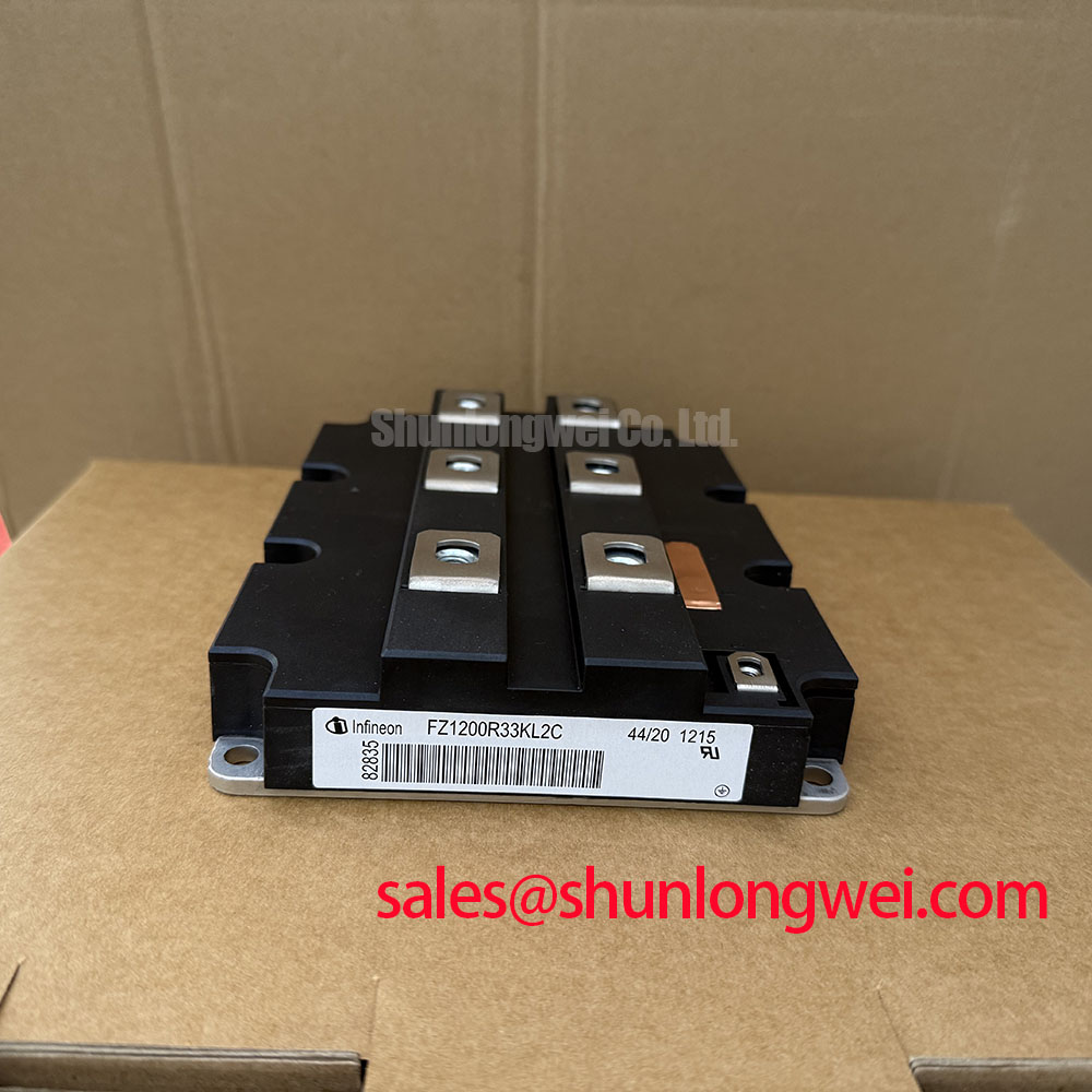
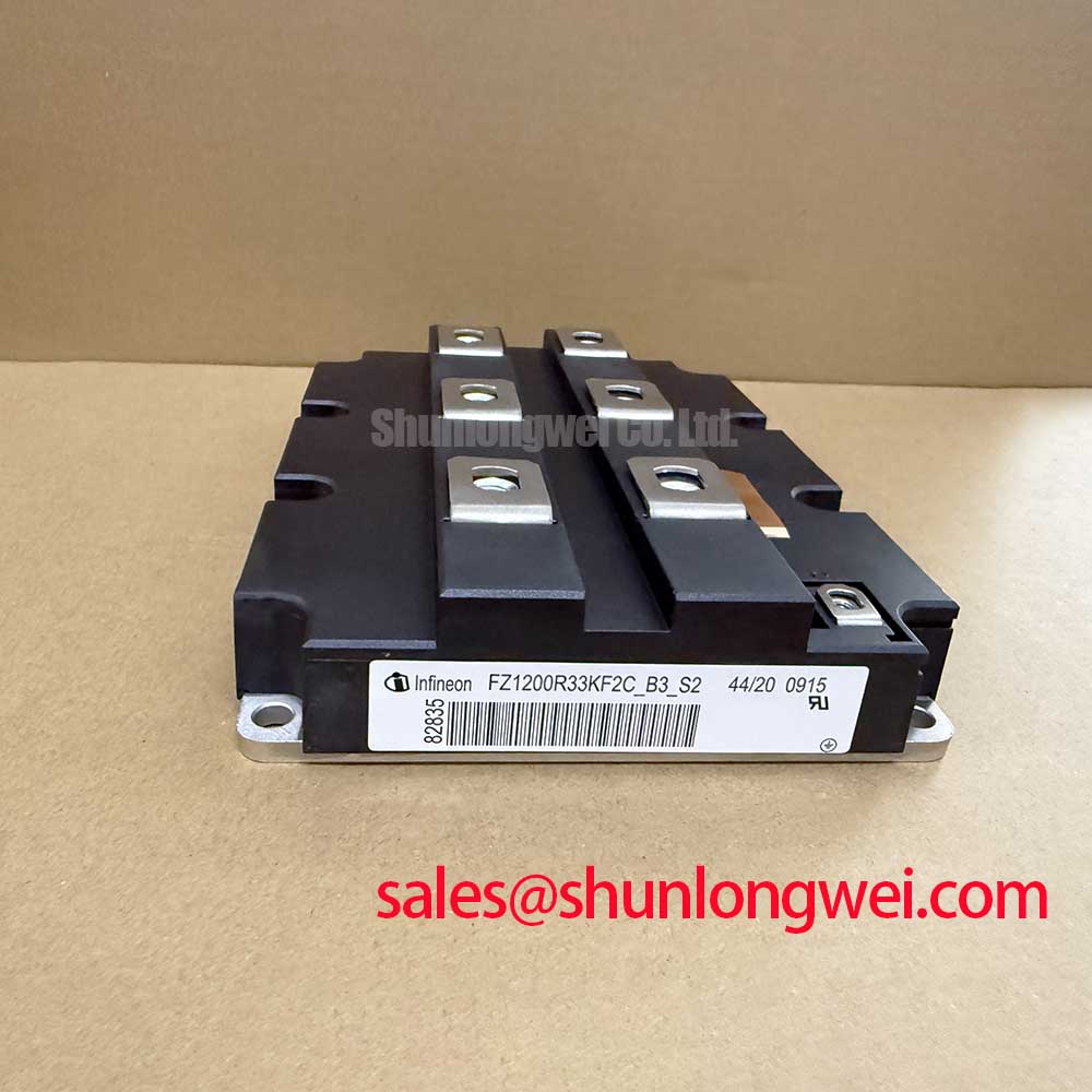
FZ1200R33KF2 Identification and Pre-Service Checks
- Isolate the equipment, verify that the DC link has discharged, and identify the collector, emitter, and gate connections from the equipment schematic before connecting test instruments.
- Check the installed module designation against FZ1200R33KF2, then compare the existing gate board, power connections, and mounting arrangement with the replacement documentation.
- Inspect the heatsink contact surface, mounting hardware, airflow path, and accessible terminals for contamination, distortion, or evidence of localized heating.
- Record the existing gate resistor configuration and protection settings before disturbing the drive circuit, so commissioning results remain traceable.
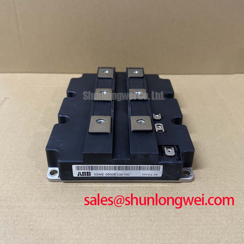
The Infineon FZ1200R33KF2 is an IGBT module with a specified voltage rating of 3300 V and current rating of 1200 A. For maintenance planning, these ratings establish the component identification baseline; gate drive compatibility, cooling performance, and protection coordination determine whether a particular installation can return to service.
| Product characteristic | Specified value | Parameter identity |
|---|---|---|
| Model | FZ1200R33KF2 | Manufacturer designation |
| Manufacturer | Infineon | Product identification |
| Rated voltage | 3300 V | Official Specification |
| Rated current | 1200 A | Official Specification |
| Package | Module | Official Specification |
| Detailed integration limits | Consult the exact manufacturer datasheet revision | Gate limits, rating conditions, switching data, terminal drawing, and assembly requirements |
FZ1200R33KF2 Operational Boundaries: Balancing Switching Dissipation and di/dt Limits
Review the external turn-on and turn-off resistor paths independently before reusing a legacy gate board. As a Design Consideration, a resistor arrangement that worked with the previous semiconductor should not automatically become the acceptance criterion for an FZ1200R33KF2 installation. Driver output impedance, gate loop routing, connection resistance, and switching conditions all influence the voltage actually delivered between gate and emitter.
Start with the circuit drawing rather than resistor markings alone. Identify separate charging and discharging paths, any steering diodes, and the return connection used by the driver. Inspect connections for looseness and verify that protection circuitry has not been bypassed during earlier repairs. A measured resistor value cannot reveal excessive inductance in a long connection or an unsuitable return path.
During controlled commissioning, compare gate voltage, collector current, and collector-emitter voltage using appropriately rated instrumentation and a measurement arrangement suited to the common-mode environment. Increasing turn-on resistance generally slows current transfer and can reduce abrupt commutation, but it can also increase switching dissipation. Turn-off resistance influences voltage overshoot and turn-off energy differently. Adjustments should therefore follow measured behavior across the intended operating conditions, not a universal resistor prescription.
Keep the gate loop compact and separate its routing from high-current switching conductors where the equipment layout permits. Preserve the specified insulation distances and physical barriers rather than moving conductors solely to shorten a connection. If ringing changes substantially when probe placement changes, examine the measurement loop before modifying the drive circuit.
For compatibility evaluation in a utility-scale centralized battery energy storage PCS, engineers should check bidirectional operating states, current direction, and the existing protection strategy. A comparison with FZ3600R17HP4B2BOSA2 belongs in a documented selection review covering electrical ratings, topology, gate requirements, and mechanical interfaces; the shared manufacturer does not establish interchangeability.
FZ1200R33KF2 Circuit Protection & Reliability: Damping Reverse-Recovery and Turn-Off Oscillations
Separate diode reverse-recovery behavior from IGBT turn-off tail current when interpreting an oscillating waveform. As a Design Consideration, these mechanisms occur during different switching events and require different checks. Where the power circuit commutates current from a freewheeling diode, reverse-recovery current can interact with circuit inductance; during IGBT turn-off, stored charge and the external circuit influence the current decay and voltage transition.
Capture the relevant commutation event with consistent current direction, temperature, and bus conditions. Evaluate the reverse-recovery current peak and its decay together with collector-emitter overshoot, rather than treating an isolated ringing trace as proof of a defective module. Diode behavior should be assessed using the actual circuit configuration and the characteristics applicable to that diode, not inferred from the module’s current rating.
An RC snubber can damp a measured resonance, but its resistance, capacitance, pulse loading, and placement must be determined from the circuit. Examine the power loop and capacitor connections before adding damping components: an unnecessarily long snubber connection can undermine the intended suppression. Compare the resulting transient reduction with snubber heating and switching loss throughout the relevant duty cycle.
Protection review should also distinguish collector-emitter saturation behavior from desaturation detection. The driver’s detection threshold, blanking interval, propagation delay, and shutdown response need coordination with the device’s documented short-circuit withstand conditions. Soft turn-off can help control fault interruption overshoot, but neither its timing nor the short-circuit safe operating area should be inferred from the 3300 V rating.
At the system level, phase-angle control and line-frequency ripple belong to the upstream converter and DC-link assessment, not to an assumed thyristor function inside this IGBT module. If an equipment drawing includes FZ400R12KS4 in a separate auxiliary or conversion stage, evaluate that stage by its own schematic and ratings. Coordinating ripple, switching transients, and protection requires understanding the actual topology, without treating a related IGBT as a rectifier substitute.
The Infineon IGBT Modules & Discretes Official Portfolio provides manufacturer context for device families. Reduced ringing is a useful engineering result, but it does not establish equipment-level EMC compliance; that requires assessment of the assembled system under its applicable requirements.
Assembly Integrity & Layout Architecture: Assessing High-Altitude Cosmic-Ray SEB Exposure for FZ1200R33KF2
Record the installation elevation and the actual blocking-voltage profile before requesting a cosmic-ray reliability assessment. As a Design Consideration, altitude-related single-event burnout evaluation is a device-specific reliability task, not an extension of routine gate resistor adjustment. A useful assessment considers operating voltage, exposure time, installation conditions, and manufacturer-supported susceptibility information.
Do not assign a failure-in-time rate or a bus-voltage derating percentage from the product designation. For a quantified assessment, obtain manufacturer reliability information applicable to the exact device and operating conditions, together with the environmental assumptions used in that assessment. An altitude value by itself does not supply the required voltage-dependent failure model.
Keep this reliability question separate from insulation coordination. Creepage, clearance, connector spacing, and enclosure arrangements must be evaluated against the applicable equipment requirements and installation environment. Cosmic-ray susceptibility and air-insulation performance are different issues; increasing physical spacing does not constitute evidence of reduced semiconductor single-event burnout susceptibility.
Maintenance records should distinguish steady blocking operation from switching overshoot and abnormal bus events. Retain voltage traces with their load conditions and instrument configuration, rather than recording only a maximum number without context. This gives the responsible engineer a usable operating profile for assessing electrical stress and deciding whether changes to the system are justified.
The related article Unlocking Efficiency in Industrial Drives offers background on a different IGBT technology discussion; it is not evidence that FZ1200R33KF2 uses that technology or shares its reliability characteristics. Use the Infineon IGBT Modules Overview to navigate manufacturer resources, while keeping any qualification or lifetime claim tied to documentation that explicitly covers the relevant device.
FZ1200R33KF2 Thermal-Electrical Optimization: Heatsink Surface Flatness and Thermal Interface Application
Inspect heatsink flatness and the module’s mounting surface before selecting a thermal interface application method. As a Design Consideration, scratches, embedded debris, residual compound, and uneven support can disrupt heat transfer even when the cooling system appears operational. Do not assume a particular baseplate material, convexity specification, or permissible deformation without the applicable mechanical documentation.
Clean the mating surfaces using methods compatible with the module and interface material. Check for burrs around threaded holes and for contamination that could hold the assembly away from the heatsink. Avoid modifying the module contact surface to make it appear flat; its specified geometry must be evaluated using the manufacturer’s inspection and mounting requirements.
Apply the approved thermal interface material using a controlled, repeatable process. Layer thickness and coverage should follow the relevant assembly specification rather than a generic grease thickness. Excess material is not a dependable remedy for poor flatness, while insufficient coverage can leave localized thermal resistance. Record the material identification and application method so later maintenance can reproduce the assembly.
Where the mounting instructions call for staged cross-pattern tightening, use a calibrated tool and the specified sequence. Keep mounting fastener requirements separate from electrical terminal torque requirements. Neither a generic bolt size nor the module’s current rating establishes the correct tightening value, and uncontrolled tightening can distort the assembly rather than improve thermal contact.
Set inspection intervals from cabinet contamination, operating duty, temperature trends, and previous service findings. Check cooling passages for dust accumulation and examine accessible interface edges for changes that warrant further inspection. In environments with temperature cycling or humidity variation, assess condensation control at the enclosure level and investigate moisture before energization.
Maintenance Note: Trend terminal temperature rise under comparable load conditions and check the cooling airflow path before attributing a temperature increase to the module itself.
After reassembly, compare temperatures at repeatable locations with the load, ambient conditions, and cooling status recorded. A warmer terminal, heatsink region, or module location may justify checking connection integrity, airflow distribution, or interface quality; none identifies a single cause on its own. Release the equipment only after the responsible engineer has reconciled the thermal observations with the electrical commissioning results and the equipment’s acceptance criteria.