 1. Overall Arrangement
We will take the Infineon FF600R17ME4 IGBT module to explain. First look at its pin definition and internal layout.
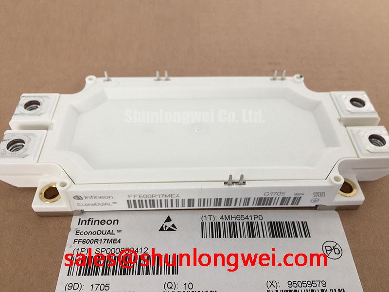
Note: The internal arrangement of the brown module is actually the corresponding model produced by Fuji, because its package and pin definition are exactly the same. There is no big difference in its internal layout.
A. The module is internally filled with a certain amount of transparent silica gel to increase the insulation performance and can be used as a buffer for vibration.
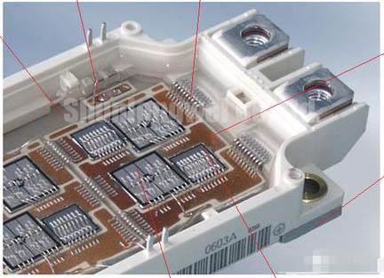
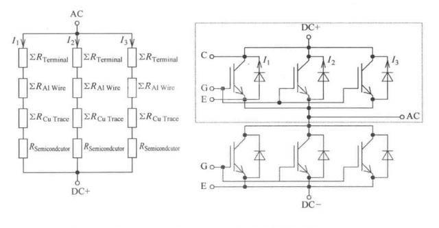
B. There is also a parallel connection inside the module, and three IGBTs and three diodes are connected in parallel inside the module.
C. The chips and chips are isolated and they are connected by bond wires.
The structure of the IGBT includes a frame and a cover plate, a chip, a bonding wire, a substrate, a substrate, and the like. The main components are briefly introduced below.
2. Plastic frame
Remarks: The frame mentioned in this article includes the cover plate, the same.
The environment in which the frame works may be at -55-150 degrees Celsius and is operated in a high temperature, high voltage environment. This requires the framework to have the following performance:
A, dimensional stability
B, high mechanical strength
C, good insulation performance (CTI requirements above 400)
D, high temperature resistance (high temperature of 250 degrees Celsius when soldering IGBT pins)
E, Good fire resistance (UL94-V0 level)
F, RoHS compliant, can not contain harmful substances such as halogen and arsenic oxide
In the long-term practice, the following plastics meet the application requirements of IGBT modules: PPS, PBT, PA, PET, etc.
3. Substrate
Basic knowledge of IGBT modules (2) Module structure
4. Substrate
The substrate is usually made of copper, has a thickness of 3-8 mm, and has a nickel plating layer of 3-10 mm.
Not all modules have a substrate, usually only medium and high power substrates, and some low power modules have no substrate.
5. Bond wire
The material of the bonding wire can be gold wire, copper wire or aluminum wire, but the current process is mainly aluminum. The bond wires are connected to other components by ultrasonic welding.
It should be noted that the number of bond wires is determined by the current through which it needs to flow, but at the same time it is affected by the resistance and thermal resistance. Since the bonding wire is welded to the DCB or the frame at one end and one end, the heat dissipation condition is good, so the temperature is the highest among them, but since the bonding wire is in the silica gel, the silica gel determines the temperature that the bonding wire can reach. online.
DCB to DCB are usually connected by bond wires, but there are other methods.
Basic knowledge of IGBT modules (2) Module structure
6. External circuit connection
There are many ways to connect external circuits, such as soldering, nut connection, spring (reed) connection, connector, crimping, etc. The failure rate of different connection methods is as follows.
6.1 bolted connection
6.2 Welding connection
6.3 plugin connection
6.4 Crimp connection
6.5 spring and reed connection
The spring and reed connection are used more in the Semikron module, mainly in the control part of the module. The SEMIKRON MiniSKiiP is connected by a spring piece; the SEMiX module uses a spring connection, a reed and a spring structure.
Spring contact connections have more advantages than solder and plug connections when board assembly
– Better use of board area and easier wiring because there is no need to punch holes.
– Simpler and easier to automate assembly, because there are no components that are inserted into the weld hole on a large scale and below a certain error requirement. – Assembly of (heavy) power semiconductors after assembly of the board and preliminary review of the heat sink.
– Higher temperature adaptability because the contact points are free to slide
– Higher impact and vibration resistance (no solder joint fatigue)
– Quasi-sealed contact, corrosion resistant
– No electronic migration