IGBT vs. MOSFET: When to Use IGBT and When to Choose MOSFET in 2025
In the world of power electronics, the choice between an Insulated Gate Bipolar Transistor (IGBT) and a Metal-Oxide-Semiconductor Field-Effect Transistor (MOSFET) is a fundamental decision that can define a system’s efficiency, cost, and reliability. While both are voltage-controlled switches, they are not interchangeable. For engineers and procurement managers, making the wrong choice can lead to thermal management nightmares, excessive power loss, or an unnecessarily expensive bill of materials. This guide will demystify the selection process, providing a clear framework based on 2024 technology trends and real-world application demands.
Understanding the Core Technology: A Tale of Two Structures
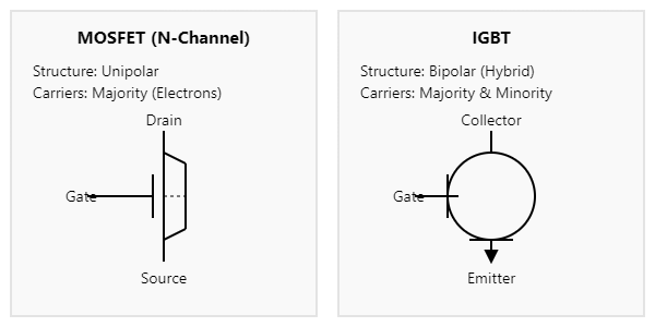
At a glance, IGBTs and MOSFETs seem similar. Both are three-terminal semiconductor devices (Gate, Collector/Drain, Emitter/Source) controlled by a gate voltage. However, their internal structures dictate their distinct performance characteristics.
A MOSFET is a purely unipolar device. Current flows through a semiconductor channel (N-channel or P-channel), and its resistance is controlled by the electric field generated by the gate voltage. This structure allows for incredibly fast switching speeds because it relies only on majority carriers (electrons in N-channel), eliminating the storage time associated with minority carriers.
An IGBT, on the other hand, is a hybrid. It combines the simple gate-drive characteristics of a MOSFET (the “Insulated Gate”) with the high current-handling and low saturation voltage capabilities of a Bipolar Junction Transistor (BJT) (the “Bipolar Transistor”). This hybrid structure means it is a bipolar device, using both majority and minority carriers for conduction. This results in lower on-state voltage drop (conduction loss) at high currents but introduces a “tail current” during turn-off, which slows down its switching speed compared to a MOSFET.
Core Comparison Analysis: IGBT vs. MOSFET Head-to-Head
To make an informed decision, it’s crucial to compare these devices across key electrical and thermal parameters. The right choice often depends on which parameter is most critical for your application. For a comprehensive overview, explore our guide on power semiconductor selection.
| Parameter | MOSFET | IGBT | Engineering Implication |
|---|---|---|---|
| Voltage Rating | Excels at <600V. High-voltage versions exist but with significantly higher RDS(on). | Dominant in applications >600V, with ratings up to 6.5kV available. | For high-voltage systems (e.g., 400V+ AC lines), IGBT is the default choice due to lower conduction losses. |
| Current Handling | Good. High-current applications often require paralleling multiple devices. | Excellent. Single IGBT modules like the CM600DX-24T can handle hundreds or thousands of amps. | IGBTs simplify design and reduce component count in high-power applications. |
| Switching Speed | Very Fast (>100 kHz, up to MHz range). Minimal turn-off delay. | Slower (Typically <50 kHz). Turn-off includes a “tail current” phase. | MOSFET is superior for high-frequency switch-mode power supplies (SMPS) and DC-DC converters to minimize switching losses. |
| Conduction Loss | Defined by RDS(on). Losses are proportional to I² * RDS(on). Rises sharply with voltage rating. | Defined by VCE(sat), a relatively fixed voltage drop. Losses are proportional to I * VCE(sat). | At high current and voltage, IGBT’s linear loss characteristic is more efficient than MOSFET’s squared loss characteristic. |
| Gate Drive | Relatively simple. Requires a gate driver to charge/discharge gate capacitance quickly. | Similar to MOSFET but often requires a higher gate voltage (e.g., +15V) and sometimes a negative gate voltage (e.g., -5V to -15V) for robust turn-off. | IGBT gate drive design can be more complex and costly to ensure reliability and prevent spurious turn-on. |
| SOA (Safe Operating Area) | Generally robust, especially against short circuits, due to its resistive nature. | Prone to latch-up under extreme conditions. Requires careful monitoring of RBSOA and SCSOA. | IGBT designs must incorporate robust protection circuits against short-circuit events. |
Application Sweet Spots: A Practical Decision-Making Guide
The theoretical comparison is useful, but the real decision comes down to your application’s specific needs. The chart below serves as a quick reference for making the initial choice.

When to Choose a MOSFET: The High-Frequency Champion
MOSFETs are the undisputed champions in applications where high switching frequency is paramount and operating voltages are relatively low.
- Switch-Mode Power Supplies (SMPS): In modern power adapters, server power supplies, and telecom rectifiers, frequencies above 100 kHz are common to shrink the size of magnetics. MOSFETs are the only viable choice here.
- Low-Voltage Motor Control: For battery-powered tools, drones, and small robotics operating below 100V, MOSFETs offer excellent efficiency and low RDS(on).
- Automotive (Low Voltage): In 12V and 48V mild-hybrid systems, MOSFETs are used extensively for controlling everything from power steering to lighting and infotainment systems.
- Class-D Audio Amplifiers: The high-frequency switching capability of MOSFETs allows for highly efficient and compact audio amplifier designs.
When to Use an IGBT: The High-Power Workhorse
IGBTs shine where high voltage and high current converge, particularly at moderate frequencies where conduction losses would cripple a MOSFET.
- Variable Frequency Drives (VFDs): The core of industrial automation. VFDs controlling AC induction motors from 1kW to several megawatts rely on robust IGBT modules like the BSM300GA120DN2 to handle the 400V/690V AC lines. Switching frequencies are typically 2-15 kHz.
- Solar Inverters and UPS: Converting high-voltage DC from solar panels or batteries into grid-compatible AC power requires high voltage blocking capability and high current capacity. IGBTs are the standard for systems over a few kilowatts.
- Electric Vehicle (EV) Main Inverters: The main traction inverter in an EV, which converts 400V or 800V DC from the battery to AC for the motor, almost exclusively uses high-performance automotive-grade IGBT or SiC modules.
- Induction Heating and Welding: These applications use resonant converters operating at 20-50 kHz. While this is high for some IGBTs, specialized high-speed modules from manufacturers like Infineon and Mitsubishi Electric are designed specifically for this “sweet spot,” offering a better compromise between switching and conduction losses than a high-voltage MOSFET.
Case Study: Optimizing a 50kW EV Fast Charger
An engineering team designing a new 50kW DC fast charger faced a classic power stage dilemma.
- Problem: The initial design used multiple high-voltage Super-Junction MOSFETs in parallel for the primary converter stage (operating at 650V). While this achieved the desired switching frequency (40 kHz), the paralleled RDS(on) still resulted in significant conduction losses (around 450W). This created a thermal bottleneck, required a large, complex heatsink, and made PCB layout difficult due to balancing issues.
- Solution: The team re-evaluated the design and opted for a single, modern IGBT power module. They selected an Infineon FF450R12KE4, a 1200V module with low VCE(sat). Although this required a slightly more robust gate driver, the benefits were substantial.
- Results:
- Reduced Conduction Loss: The IGBT module’s conduction loss was calculated to be ~320W under the same conditions, a reduction of nearly 30%.
- Simplified Thermal Management: Replacing multiple discrete components with a single power module allowed for a much simpler, more effective, and more reliable thermal interface to the heatsink.
- Reduced Assembly Cost: The component count dropped significantly, reducing both PCB complexity and assembly time.
- Improved Reliability: The integrated nature of the IGBT module provided better-matched components and a higher specified power cycling capability, leading to a more robust final product.
Final Verdict: It’s About the Application, Not the Device
The “IGBT vs. MOSFET” debate doesn’t have a universal winner. The superior device is the one that best fits the voltage, current, and frequency requirements of your specific application. As a rule of thumb for 2024 designs:
- Start with Voltage: If your bus voltage is above 600V, your first thought should be an IGBT. Below 200V, a MOSFET is almost always the answer. The 200V-600V range is the primary battleground where a detailed loss analysis is required.
- Then Consider Frequency: If you need to switch faster than 50-100 kHz, lean heavily towards a MOSFET. For frequencies below 20 kHz, the IGBT’s lower conduction loss will likely dominate.
- Finally, Evaluate Power Level: For multi-kilowatt systems, the power density and thermal performance of an IGBT module are often far superior to a solution using many discrete MOSFETs in parallel.
By following this structured approach, you can confidently select the right power switch, ensuring your design is efficient, cost-effective, and reliable. For specific project requirements or to source a wide range of industry-leading IGBT modules, our team of application experts is ready to assist.